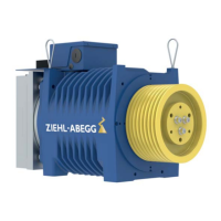
Figure 5-5-4-2-01 - Simplified diagram for brake control
(1) Voltage supply
(2) Button two circuit test
(3) / (4) “Open brake” button
(5) Rectifier
(K3) Brake contactor, activated by safety circuit
(K4) Brake contactor, activated by control or frequency inverter
5.5.5 Connection
•
The terminal box for the brake may be removed from the elevator machine and mounted on site for
a better attainability.
•
The brake is only allowed to be supplied with power when fastened to the motor and after having
connected the protective conductor of the motor at the control and the motor side.
•
The brakes must be protected with varistors against overvoltage from switching operations. The
varistor must lie directly on the coil or its connections.
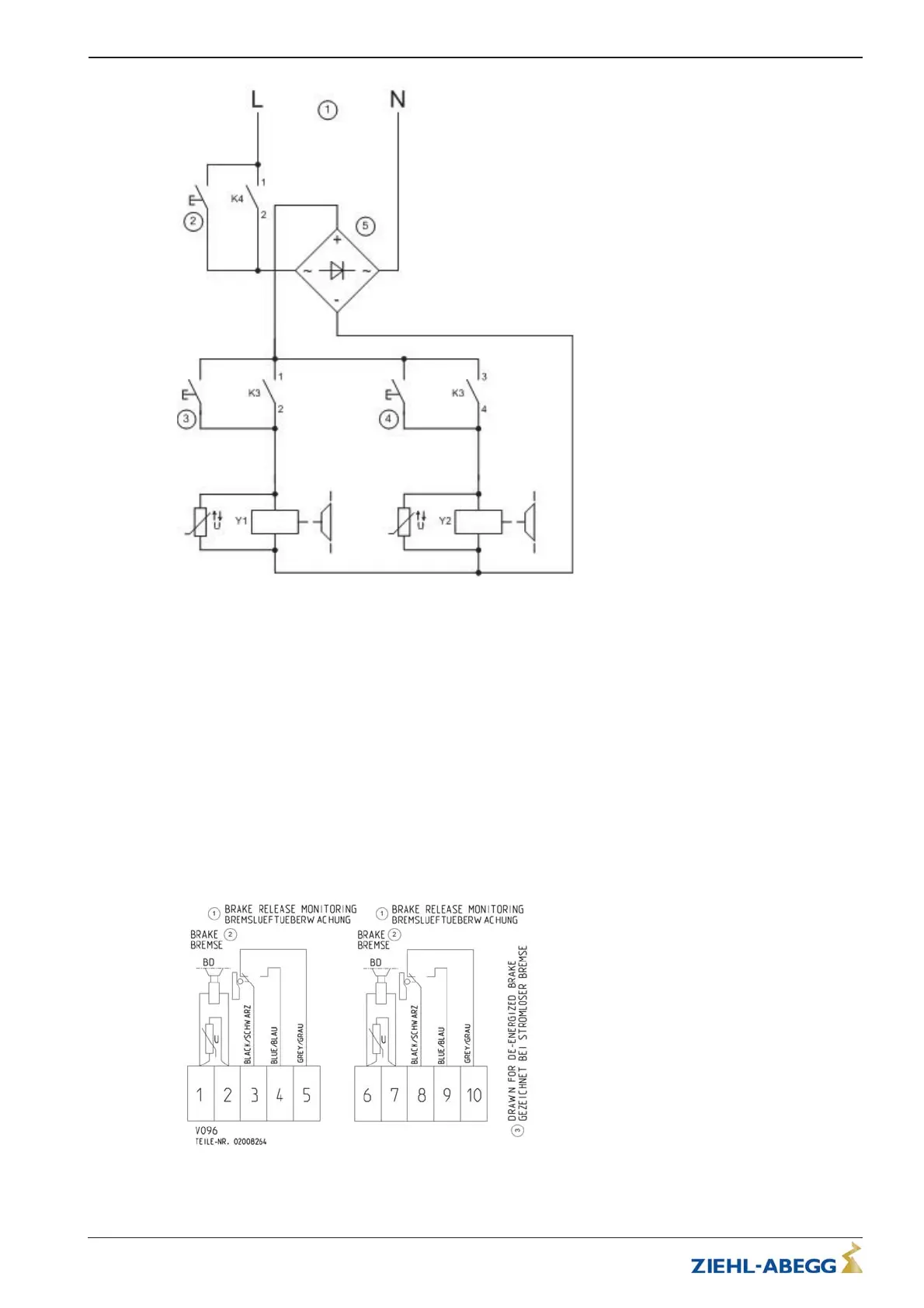
5.5.6 Connection diagram
Brake wiring diagram with micro switch
Figure 5-5-6-01
(1) Brake release monitoring
(2) Brake
(3) Shown with currentless brake
Translation of the original operating instructions
ZAtop – model series SM200.40E/SM200.45E Electrical installation
A-TBA21_01-GB 2021/30 Index 003 Part.-No. 01013507-GB (EU-BD 1112)
21/64
 Loading...