EasyManuals Logo

ABB 630 series Installation Manual

ABB 630 series
96 pages
To Next Page IconTo Next Page
To Previous Page IconTo Previous Page
Page #31 background imageLoading...
Page #31 background image
6. Tighten the screws.
7. Mount the IEDs with the rack mounting panels to the 19" rack.
8. Tighten the screws.
GUID-95B1F568-4B1C-4758-B370-661C286F1BC4 V1 EN
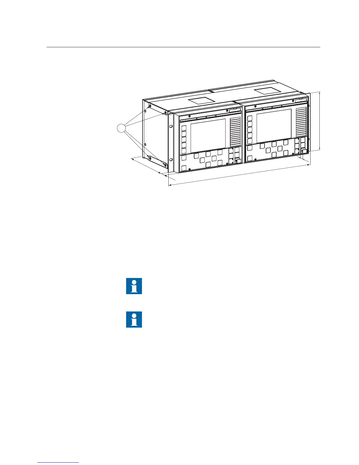
Figure 9: Two rack mounted IEDs side by side
A
224 mm 1 Screws
B 25.5 mm
C 482.6 mm (19")
D 13 mm
E 177mm (4U)
Make sure that the lower venting holes in the IED is not obstructed.
Check the allowed minimum bending radius from the optical cable
manufacturer.
4.3.3.3 Rack mounting a single IED and test switch RTXP
1. Attach the mounting bracket to the left side of the IED using the required screws.
2. Tighten the screws.
3. Remove the four plastic plugs from the right side of the IED and attach the
mounting bracket securely using the required screws.
4. Tighten the screws.
1MRS755958 C Section 4
Mounting
630 series 23
Installation Manual

Table of Contents

Other manuals for ABB 630 series

Questions and Answers:

Question and Answer IconNeed help?

Do you have a question about the ABB 630 series and is the answer not in the manual?

ABB 630 series Specifications

General IconGeneral
Frequency50/60 Hz
Protection FunctionsOvercurrent, earth fault
Communication ProtocolsModbus
EnclosureIP20
TypeProtection relay

Related product manuals