GUID-56FBFBB8-3388-4473-AF87-B725AFEF57BA V2 EN
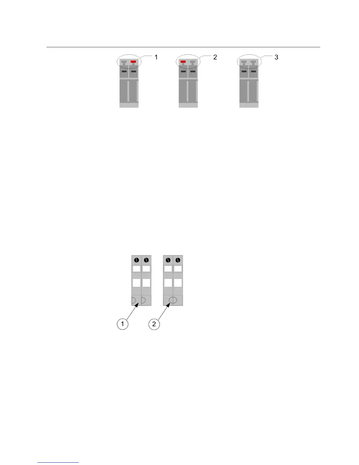
Figure 23: Fixed CT/VT Connector coding
1 CT connector coding
2 VT connector coding
3 Empty connector
5.4.1 Connecting current and voltage inputs
Connect the wires from the CTs/VTs to the correct device according to the phase
order and the connection diagram. Each terminal for CTs/VTs is dimensioned for
one 0.5...6.0 mm
2
wire or for two wires of maximum 2.5 mm
2
.
To help connecting the current and voltage inputs, the connector pair is marked
with symbols. For a current input, the connector pair forms a circle. But in the case
of a voltage input, the connector pair forms two half-circles.
GUID-61D346C6-30D8-468A-8641-654864811C53 V1 EN
Figure 24: CTVT connector symbols
1
VT symbol
2 CT symbol
1MRS755958 C Section 5
Connecting
630 series 41
Installation Manual
 Loading...