The secondary device acts as Backup Link Master on each H1 link attempting to take
over the LAS role if required. Additional Link Master devices may be configured to act
as Backup Link Master on the H1 links.
The two devices forming a redundant set communicate via a redundancy link interface
and via Ethernet. This interface is used to establish a redundant set of devices, to
exchange signs of life, and to control redundancy switch-over, while the Ethernet is used
to transfer configuration information from the primary device to the secondary device.
Therefore, both an operational serial communication path and an operational Ethernet
path between both devices are required for proper operation.
The two physical Linking Devices forming a redundant set of devices are determined by
the redundancy link between them. Without that redundancy link, both devices operate
like independent, non-redundant primary devices.
B.6.2 Fault Domain
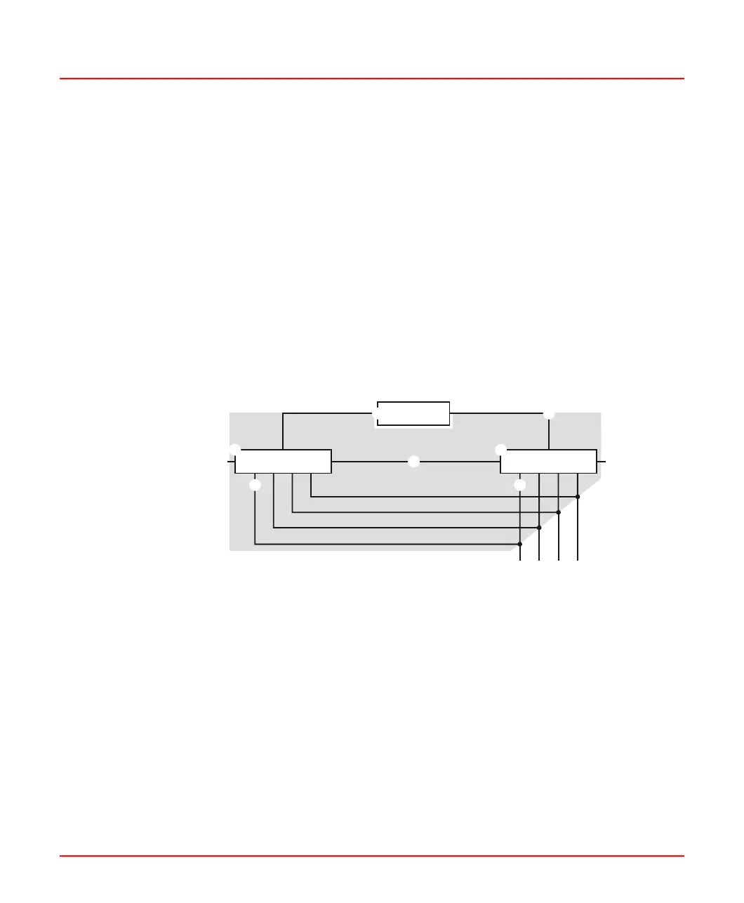
Hub/Switch
Redundancy Link Interface
Power Supply Power Supply
Linking Device 1
Linking Device 2
H1 Links
HSEHSE
Figure B.2: Fault Domain
The shaded area in Figure B.2 shows the fault domain. Faults within the fault domain
can be detected and covered by the redundancy features. Those are:
• permanent faults within the Linking Device (1)
• transient faults within a Linking Device that lead to loss of functions (1)
• a loss of the serial connection between the two Linking Devices (2)
2PAA114135-610 106
B Technical Reference
B.6 Redundancy

 Loading...