E-Clipse Bypass Configurations for ACH550 Drives 13
Installation
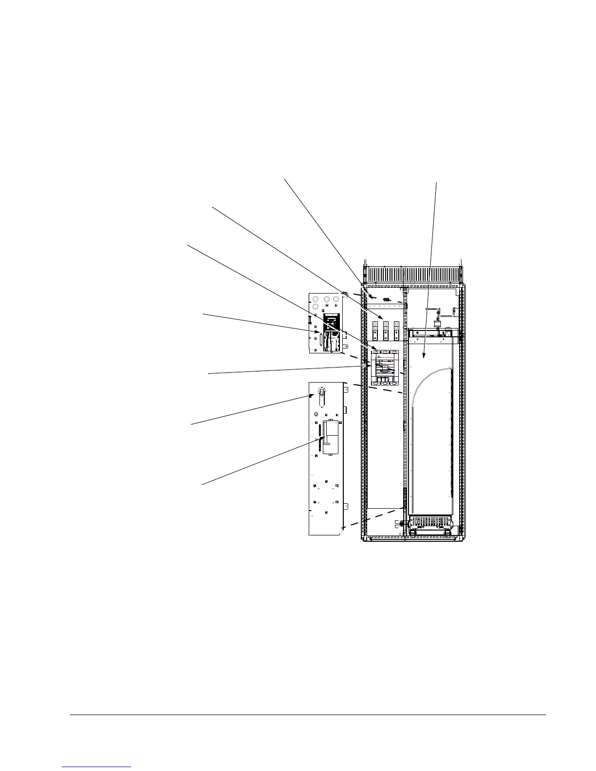
Connection Diagrams – Standard E-Clipse Bypass (R8, Floor Mounted)
ACH550 Standard E-Clipse Bypass units are configured for wiring access from the
top. The following figure shows the Standard E-Clipse Bypass (floor mounted) wiring
connection points. Refer to the ACH550-UH User's Manual for control connections
to the drive.
ACH550 Drive
E-Clipse Bypass
Control Board
Terminals ( x2)
Disconnect Switch
or Circuit Breaker
Ground Lug Bar
Input Power
Terminals
Motor Terminals
Service Switch
(optional)
ACH550
Control Board
Terminals ( x1)

 Loading...


