E-Clipse Bypass Configurations for ACH550 Drives 31
Installation
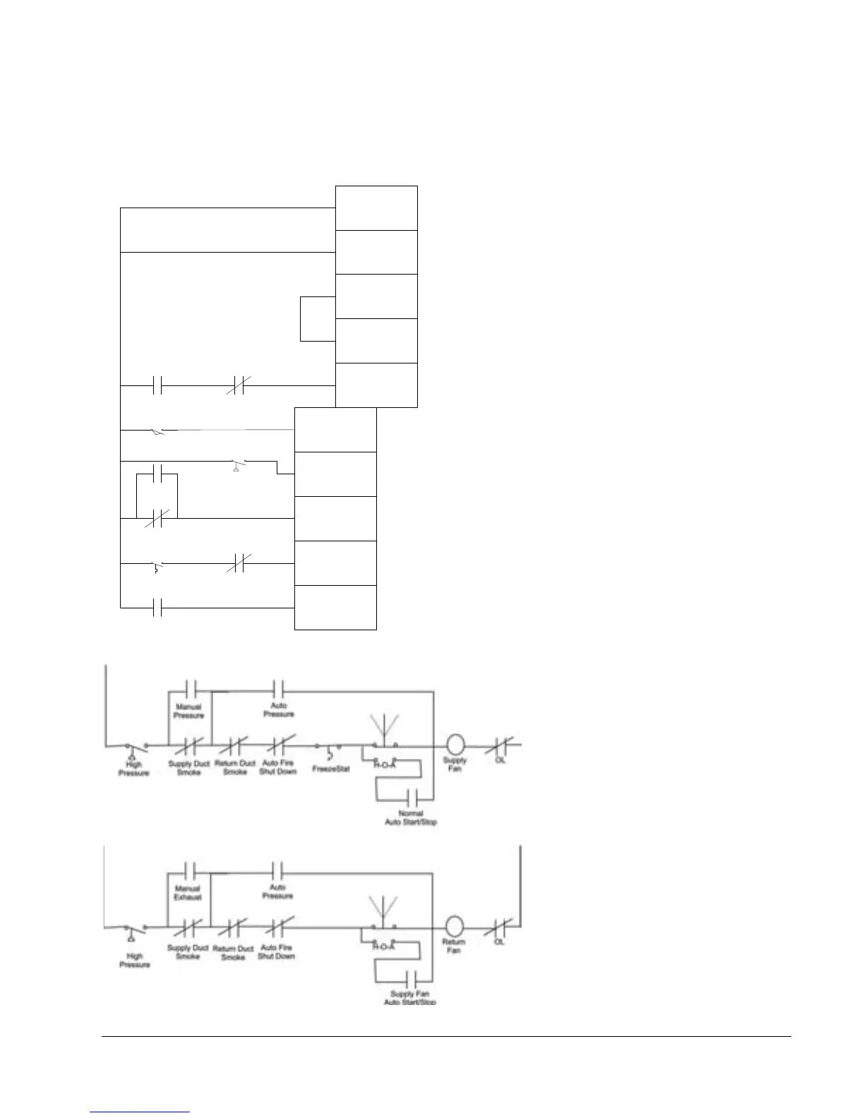
Typical Wiring Diagrams Showing a Conventional Starter Wiring and Use of the
E-Clipse Bypass
Typical system wiring with use of E-Clipse Bypass:
Typical Starter Wiring for a Smoke Control listed System Today:
Auto Fire
Shut Down
Normal
Auto Start /Stop
Auto
Pressure
Return Duct
Smoke
Damper
End Switch
Supply Duct
Smoke
Manual
Pressure
High
Pressure
Freezestat
10
1
2
3
4
5
9
8
7
6
Normal Operation:
• Close Start/Stop (X2:5)
• Fan starts, assuming
that X2: 6, 7, 8, and 9
are all closed
Emergency Shutdown:
• Open auto fire
shutdown, unit stops
Smoke Control Mode:
• Close contact on X2:10
• Fan starts regardless of
position of internal HOA
switch and inputs
X2:5 and X2:9
• Inputs X2:6, 7 and 8
followed
• Internal overloads
followed
(DI1) Start/Stop
(DI2) Run
Enable
(DI3) High
Priority
Safeties
(DI4) Emergency
Shutdown
(DI5) Low
Priority
Safeties
(DI6) Smoke
Control
X2 E-Clipse Bypass Controller Input
Notes:
1. Pressure cutouts, duct smoke detectors
and auto shutdown are
2-pole.
2. Manual control also activates “auto
control” relays.

 Loading...


