E-Clipse Bypass Configurations for ACH550 Drives 7
Installation
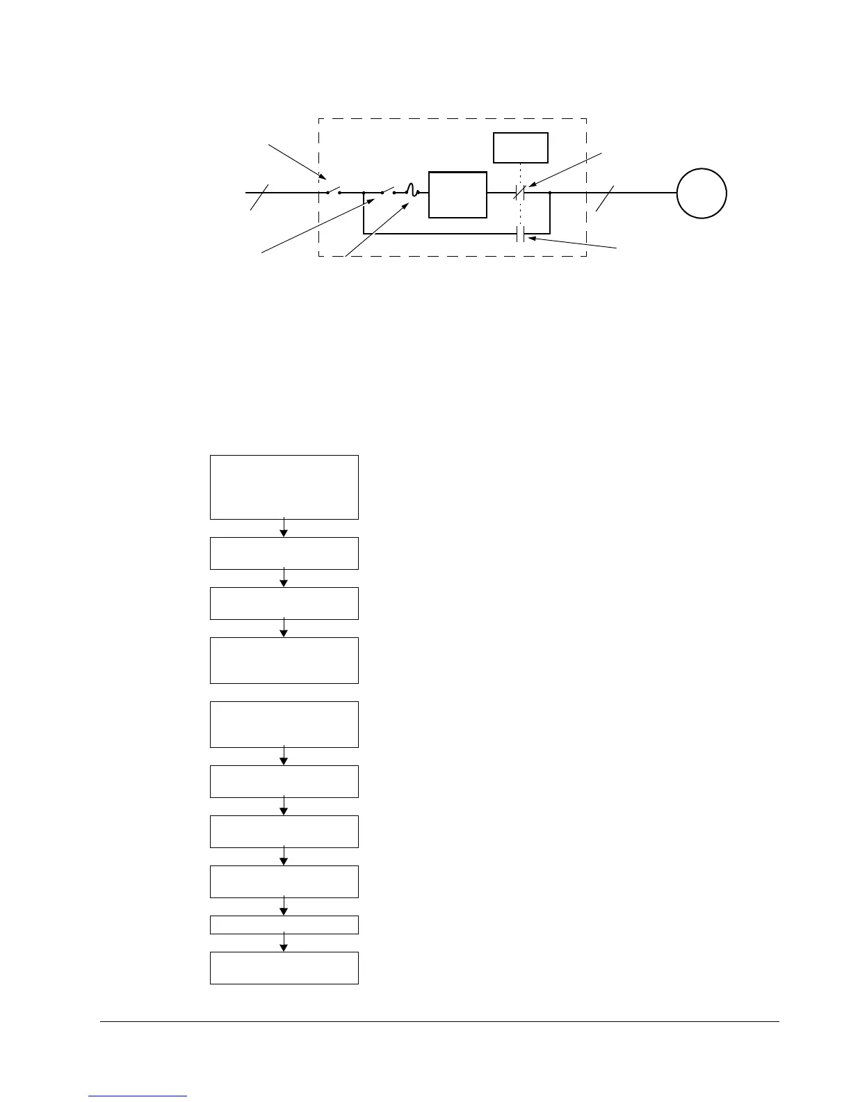
The following is a typical power diagram.
Installation Flow Chart
The installation of E-Clipse Bypass Configurations for ACH550 drives follows the
outline below. The steps must be carried out in the order shown. At the right of each
step are references to the detailed information needed for the correct installation of
the unit.
Task
Reference in ACH550-UH
User’s Manual
“Installation” section
Reference in this Manual
PREPARE for installation “Preparing for Installation” "Drive Identification" on page 8.
"Suitable Mounting Location
(Supplement to ACH550-UH User’s
Manual)" on page 9
PREPARE the Mounting
Location
“Prepare the Mounting
Location”
—
MOUNT the unit — “Mount the Drive with E-Clipse
Bypass”
REMOVE the covers
from Vertical E-Clipse
Bypass Unit
“Remove Front Cover” “Remove Vertical E-Clipse Bypass
Cover”
INSTALL wiring “Wiring Overview” and
“Install the Wirings on Vertical
Units”
"Installing the Wiring (Supplement to
ACH550-UH User’s Manual)"
starting on page 9.
CHECK jumpers and
switches
— "Check E-Clipse Bypass Jumpers
and Switches" on page 25.
CHECK installation “Check Installation” "Initial Settings and Checks" on page
19.
RE-INSTALL the covers “Re-install Cover” “Re-install Vertical E-Clipse Bypass
Cover”
APPLY power “Apply Power” —
START-UP “Start-Up” "Overview of Bypass Functionality"
on page 33.
ACH550
Drive with E-Clipse Bypass
Motor
3 Phase
Drive
3
3
Disconnect Switch
or Circuit Breaker
Service Switch
(Optional)
Input Power
Bypass
Contactor
Bypass
Control
Drive Output
Contactor
Drive Input Fuse

 Loading...


