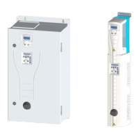
E-Clipse Bypass Configurations for ACH550 Drives 1
Safety
Safety
WARNING! The ACH550 adjustable speed AC drive with E-Clipse Bypass
should ONLY be installed by a qualified electrician.
WARNING! Even when the motor is stopped, dangerous voltage is present at
the Power Circuit terminals U1, V1, W1 and U2, V2, W2 and, depending on the
frame size, UDC+ and UDC-, or BRK+ and BRK-.
WARNING! Dangerous voltage is present when input power is connected.
After disconnecting the supply, wait at least 5 minutes (to let the intermediate
circuit capacitors discharge) before removing the cover.
WARNING! Even when power is removed from the input terminals of the
ACH550, there may be dangerous voltage (from external sources) on the
terminals of the relay outputs.
WARNING! When the control terminals of two or more drive units are
connected in parallel, the auxiliary voltage for these control connections must
be taken from a single source which can either be one of the units or an
external supply.
WARNING! The ACH550 will start up automatically after an input voltage
interruption if the external run command is on.
WARNING! When the ACH550 with E-Clipse Bypass is connected to the line
power, the Motor Terminals T1, T2, and T3 are live even if the motor is not
running. Do not make any connections when the ACH550 with E-Clipse
Bypass is connected to the line. Disconnect and lock out power to the drive
before servicing the drive. Failure to disconnect power may cause serious
injury or death.
Note! For more technical information, contact the factory or your local ABB sales
representative.

 Loading...