ACH550 Installation, Operation and Maintenance Manual 13
ACH550-UH
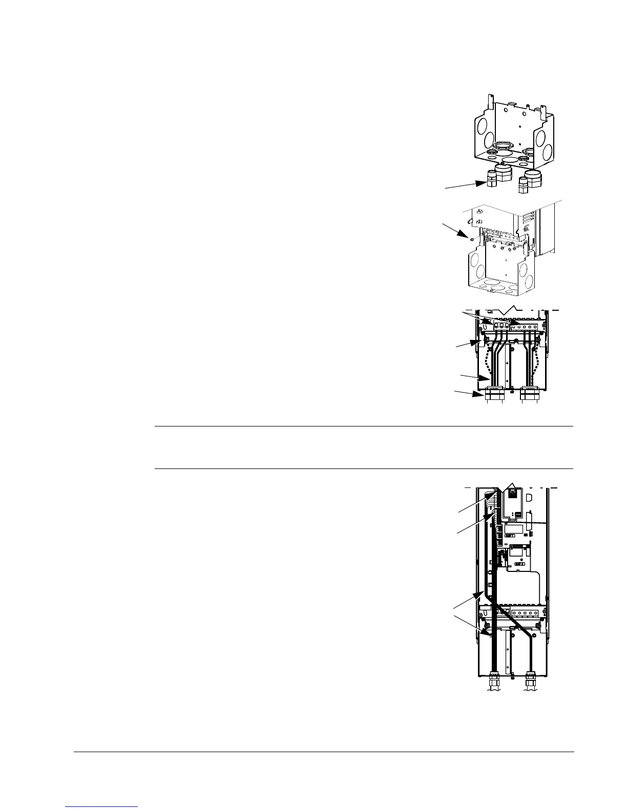
R1…R6, wiring UL type 1 enclosure
1. Open the appropriate knockouts in the
conduit box. (See Conduit kit on page 7.)
2. Install thin-wall conduit clamps (not supplied).
3. Install conduit box.
4. Connect conduit runs for input power, motor
and control cables to the box.
5. Route input power and motor wiring through
separate conduits.
6. Strip wires.
7. Connect power, motor, and ground wires to
the drive terminals.
Note: For R5 frame size, the minimum power cable size is 25 mm
2
(4 AWG). For R6
frame size, refer to Power terminal considerations – R6 Frame size on page 16.
8. Route the control cables through the conduit
(not the same conduit as either input power or
motor wiring).
9. Use available secure points and tie strap
landings to permanently secure control wiring
at a minimum distance of 6 mm (1/4") from
power wiring.
10. Strip the control cable sheathing and twist the
copper screen into a pig-tail.
11. Connect the ground screen pig-tail for digital
and analog I/O cables at X1-1. (Ground only
at drive end.)
12. Connect the ground screen pig-tail for RS485
cables at X1-28 or X1-32. (Ground only at
drive end.)
13. Strip and connect the individual control wires to the drive terminals.
14. Install the conduit box cover (1 screw).

 Loading...


