14 ACH550 Installation, Operation and Maintenance Manual
ACH550-UH
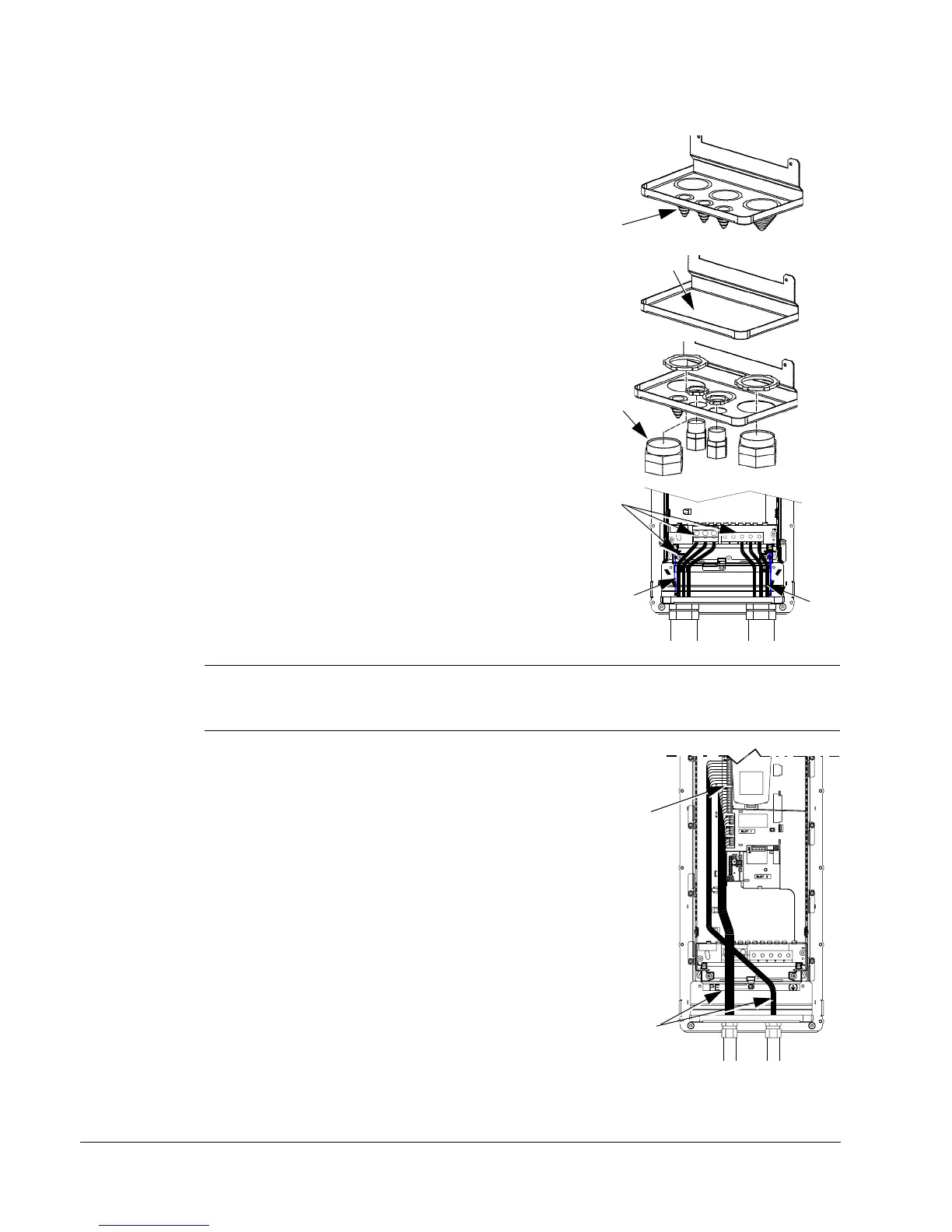
R1…R6, wiring UL type 12 enclosure
1. Step depends on Frame Size:
• Frame Sizes R1…R4: Remove and discard the
cable seals where conduit will be installed. (The
cable seals are cone-shaped, rubber seals on
the bottom of the drive.)
• Frame Sizes R4 and R5: Use punch to create
holes for conduit connections as needed.
2. For each conduit run (input power, motor and
control wiring must be separate), install liquid tight
conduit connectors (not supplied).
3. Route the power wiring through conduit.
4. Route the motor wiring through conduit (not the
same conduit as input power wiring run).
5. Strip the wires.
6. Connect the power, motor, and ground wires to
the drive terminals.
Note: For R5 frame size, the minimum power cable size is 25 mm
2
(4 AWG). For R6
frame size, refer to Power terminal considerations – R6 Frame size on page 16.
7. Route the control cables through the conduit (not
the same conduit as either input power or motor
wiring runs).
8. Use available secure points and tie strap landings to
permanently secure control wiring at a minimum
distance of 6 mm (1/4") from power wiring.
9. Strip the control cable sheathing and twist the
copper screen into a pig-tail.
10. Connect the ground screen pig-tail for digital and
analog I/O cables at X1-1. (Ground only at drive
end.)
11. Connect the ground screen pig-tail for RS485 cables
at X1-28 or X1-32. (Ground only at drive end.)
12. Strip and connect the individual control wires to the drive
terminals.
13. Install the conduit box cover (1 screw).

 Loading...


