16 ACH550 Installation, Operation and Maintenance Manual
ACH550-UH
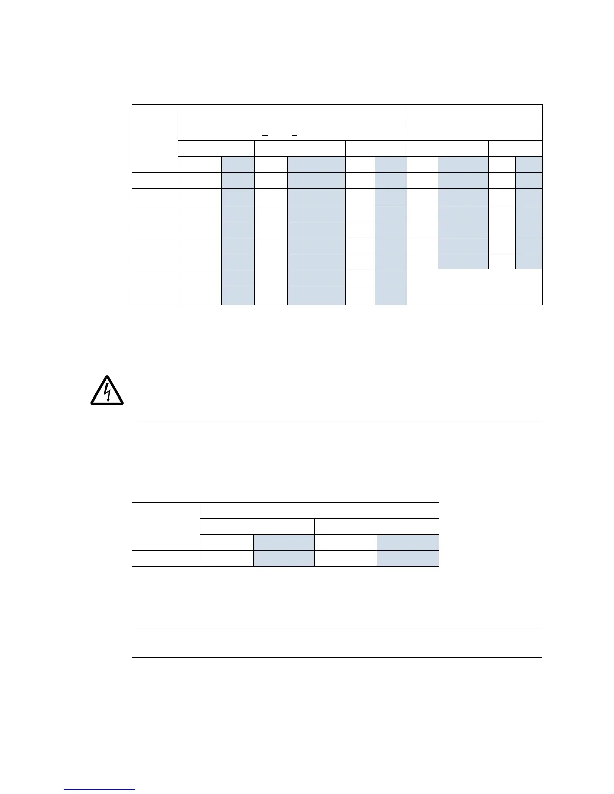
Drive’s power connection terminals
The following table provides specifications for the drive’s power connection terminals.
1. Do not use aluminum cable with frame sizes R1…R4.
2. See the following section for smaller wire sizes on frame size R6.
Power terminal considerations – R6 Frame size
WARNING! For R6 power terminals, if compression lugs are supplied, they can only
be used for wire sizes that are 95 mm
2
(3/0 AWG) or larger. Smaller wires will loosen
and may damage the drive, and require ring lugs as described below.
On the R6 frame size, if the cable size used is less than 95 mm
2
(3/0 AWG) or if no
compression lugs are supplied, use ring lugs.
Drive’s control connection terminals
The following table provides specifications for the drive’s control terminals
Control terminal descriptions
The following full-page diagram provides a general description of the control
terminals on the drive.
Note: Terminals 3, 6, and 9 are at the same potential.
Note: For safety reasons the fault relay signals a “fault” when the ACH550 is
powered down.
Frame
Size
U1, V1, W1
U2, V2, W2
BRK+
, UDC+ Terminals
Earthing PE Terminal
Min. Wire Size Max. Wire Size Torque Max. Wire Size Torque
mm
2
AWG mm
2
AWG Nm lb-ft mm
2
AWG Nm lb-ft
R1
Note 1
0.75 18 16 61.311661.31
R2
Note 1
0.75 18 16 61.311661.31
R3
Note 1
2.5 14 25 32.722532.72
R4
Note 1
10 8501/0 5.6 4501/0 5.6 4
R5 16 6702/0 15 11 70 2/0 15 11
R6 95
Note 2
3/0 185 350 MCM 40 30 185 350 MCM 40 30
R7 16
6185350 MCM 40 30 Attach appropriate ring lugs to
ground wires and mount with,
up to five 13/32 bolts.
R8 16 62x2402x500 MCM 57 42
Frame Size
Control
Maximum Wire Size Torque
mm
2
AWG Nm lb-ft
All 1.5
16 0.4 0.3

 Loading...


