ACH550 Installation, Operation and Maintenance Manual 17
ACH550-UH
1 Digital input impedance 1.5 k. Maximum voltage for digital inputs is 30 V.
2 Default values depend on the macro used. Values specified are for the HVAC default macro.
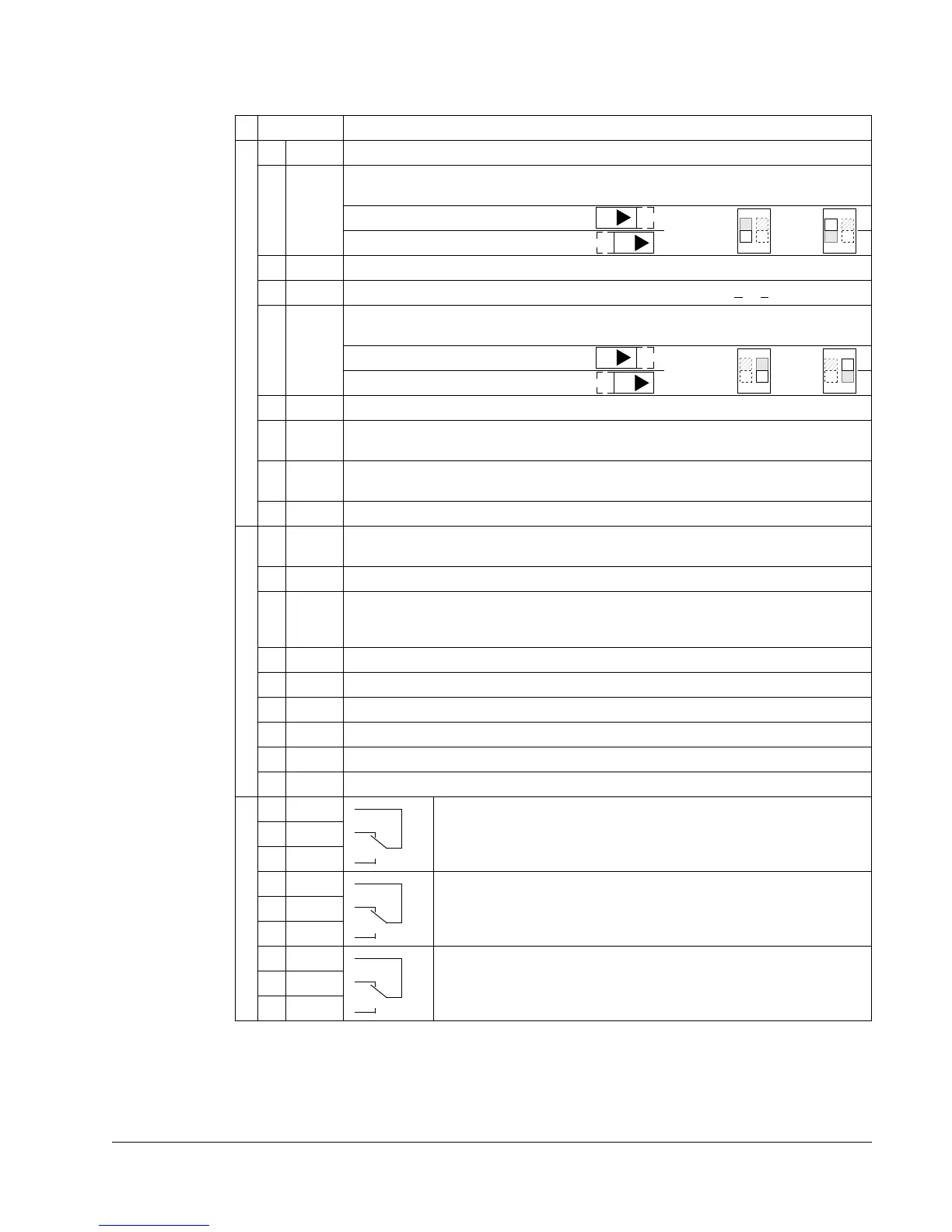
X1 Drive Control Terminal Description
1 SCR Terminal for signal cable screen. (Connected internally to chassis ground.)
2 AI1 Analog input channel 1, programmable. Default
2
= external reference. Resolution
0.1%, accuracy ±1%.
J1:AI1 OFF: 0(2)…10 V (R
i
=312k)
J1:AI1 ON: 0(4)…20 mA (R
i
=100)
3 AGND Analog input circuit common (connected internally to chassis gnd. through 1 M).
4 +10 V Potentiometer reference source: 10 V ±2%, max. 10 mA (1k <
R < 10k).
5 AI2 Analog input channel 2, programmable. Default
2
= PID feedback. Resolution 0.1%,
accuracy ±1%.
J1:AI2 OFF: 0(2)…10 V (R
i
=312k)
J1:AI2 ON: 0(4)…20 mA (R
i
=100)
6 AGND Analog input circuit common (connected internally to chassis gnd. through 1 M).
7 AO1 Analog output, programmable. Default
2
= frequency. 0…20 mA (load < 500 ).
Accuracy ±3% full scale.
8 AO2 Analog output, programmable. Default
2
= current. 0…20 mA (load < 500 ).
Accuracy ±3% full scale.
9 AGND Analog output circuit common (connected internally to chassis gnd. through 1 M).
10 +24V Auxiliary voltage output 24 VDC / 250 mA (reference to GND), short circuit
protected.
11 GND Auxiliary voltage output common (connected internally as floating).
12 DCOM Digital input common. To activate a digital input, there must be 10 V
(or -10 V) between that input and DCOM. The 24 V may be provided by the
ACH550 (X1-10) or by an external 12…24 V source of either polarity.
13 DI1 Digital input 1, programmable. Default
2
= start/stop.
14 DI2 Digital input 2, programmable. Default
2
= not configured.
15 DI3 Digital input 3, programmable. Default
2
= constant (preset) speed.
16 DI4 Digital input 4, programmable. Default
2
= safety interlock.
17 DI5 Digital input 5, programmable. Default
2
= not configured.
18 DI6 Digital input 6, programmable. Default
2
= not configured.
19 RO1C Relay output 1, programmable. Default
2
= Ready
Maximum: 250 VAC / 30 VDC, 2 A
Minimum: 500 mW (12 V, 10 mA)
20 RO1A
21 RO1B
22 RO2C Relay output 2, programmable. Default
2
= Running
Maximum: 250 VAC / 30 VDC, 2 A
Minimum: 500 mW (12 V, 10 mA)
23 RO2A
24 RO2B
25 RO3C Relay output 3, programmable. Default
2
= Fault (-1)
Maximum: 250 VAC / 30 VDC, 2 A
Minimum: 500 mW (12 V, 10 mA)
26 RO3A
27 RO3B
ON
12
or, for OFF
ON
12
for ON
ON
12
or, for OFF
ON
12
for ON

 Loading...


