8 ACH550 Installation, Operation and Maintenance Manual
ACH550-UH
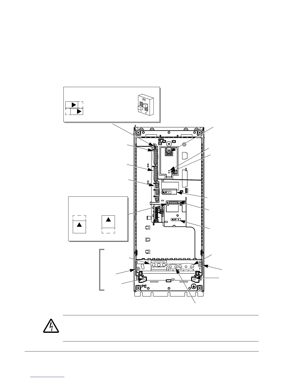
Connection diagrams
The following diagrams show:
• The terminal layout for frame size R3, which, in general, applies to frame sizes
R1
…R6, except for the R5/R6 power and ground terminals.
• The R5/R6 power and ground terminals.
• The terminal layout for R7/R8.
WARNING! To avoid danger, or damage to the drive, on IT systems and corner
grounded TN systems, see section Disconnecting the internal EMC filter on
page 10.
Panel Connector
Power LED (Green)
Fault LED (Red)
Optional Module 1
X1 – Communications
Optional Module 2
GND
Power Output to Motor
Power Input
EM1
X1 – Analog Inputs and Outputs
X1 – Digital Inputs
X1 – Relay Outputs
(and 10 V Ref. Voltage Output)
(and 24 V Aux. Voltage Output)
EM3
PE
(U1, V1, W1)
(U2, V2, W2)
X0003
(RS485)
R5/R6 differ.
See next page.
Frame Sizes
R1…R4 (Diagram shows the R3 frame.)
J2 – DIP Switches
J2
ON
off position on position
for RS485 Termination
J2
ON
Terminals Not Used
J1 – DIP Switches for Analog Inputs
AI1: (in Voltage Position)
AI2: (in Current Position)
ON
ON
The switch is one of two types:
Alternate
Original
Illustration of available switch
positions; not default settings
Illustration of available switch
positions; not default settings

 Loading...


