18 ACH550 Installation, Operation and Maintenance Manual
ACH550-UH
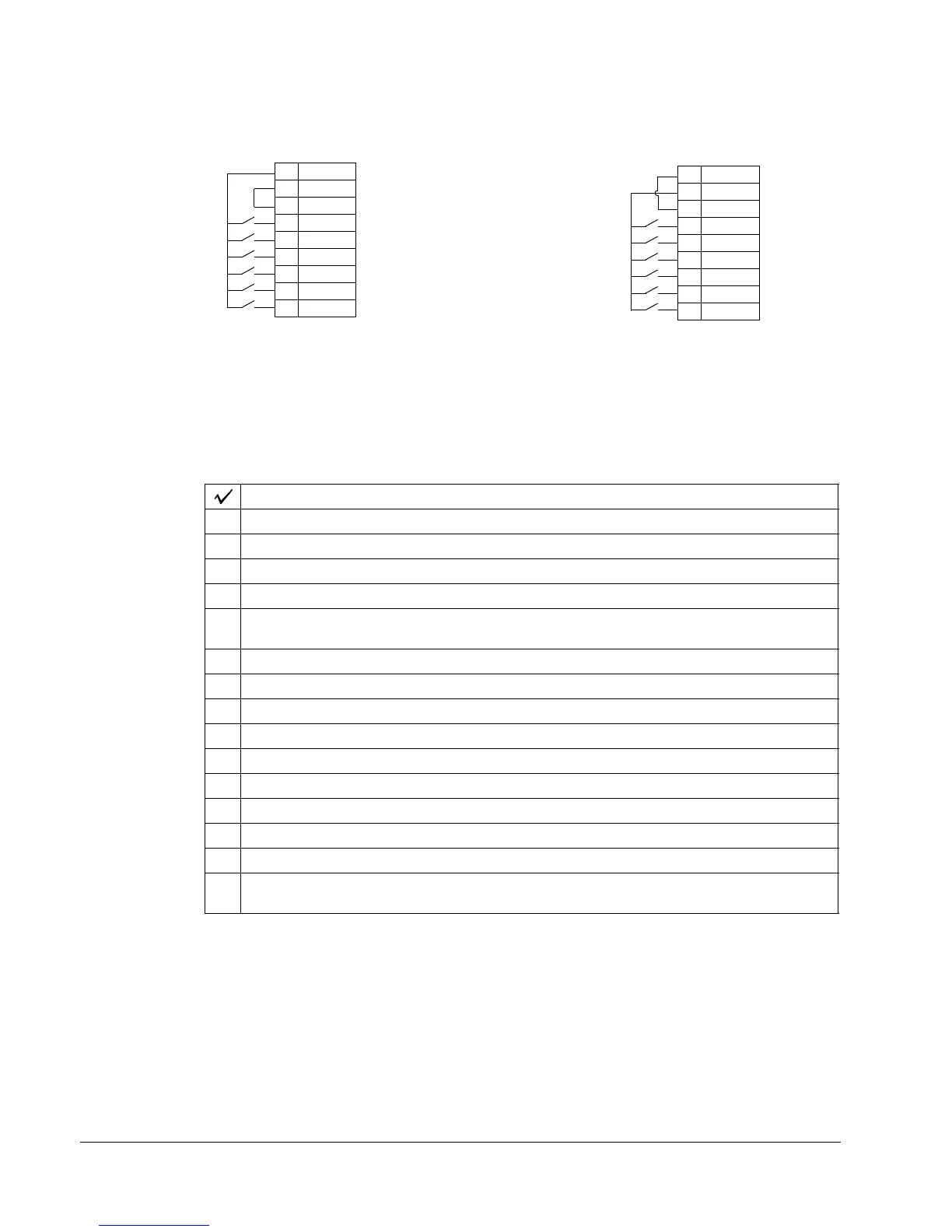
You can wire the digital input terminals in either a PNP or NPN configuration.
Serial communications
Terminals 28
…32 provide RS485 serial communication connections used to control
or monitor the drive from a fieldbus controller.
6. Check installation
Before applying power, perform the following checks.
7. Re-install cover
Check
Installation environment conforms to the drive’s specifications for ambient conditions.
The drive is mounted securely.
Space around the drive meets the drive’s specifications for cooling.
The motor and driven equipment are ready for start.
For floating networks (R1…R6): The internal RFI filter is disconnected (screws EM1 & EM3 or
F1 & F2).
The drive is properly grounded.
The input power voltage matches the drive nominal input voltage range.
The input power connections at U1, V1, and W1 are connected and tightened as specified.
The input power branch circuit protection is installed.
The motor connections at U2, V2, and W2 are connected and tightened as specified.
The input power, motor and control wiring are routed through separate conduit runs.
NO power factor compensation capacitors are in the motor cable.
The control connections are connected and tightened as specified.
NO tools or foreign objects (such as drill shavings) are inside the drive.
NO alternate power source for the motor (such as a bypass connection) is connected – no
voltage is applied to the output of the drive.
NPN connection (sink)PNP connection (source)
10 +24V
11 GND
12 DCOM
13 DI1
14 DI2
15 DI3
16 DI4
17 DI5
18 DI6
10 +24V
11 GND
12 DCOM
13 DI1
14 DI2
15 DI3
16 DI4
17 DI5
18 DI6
X1
X1

 Loading...


