Optional I/O extension modules 169
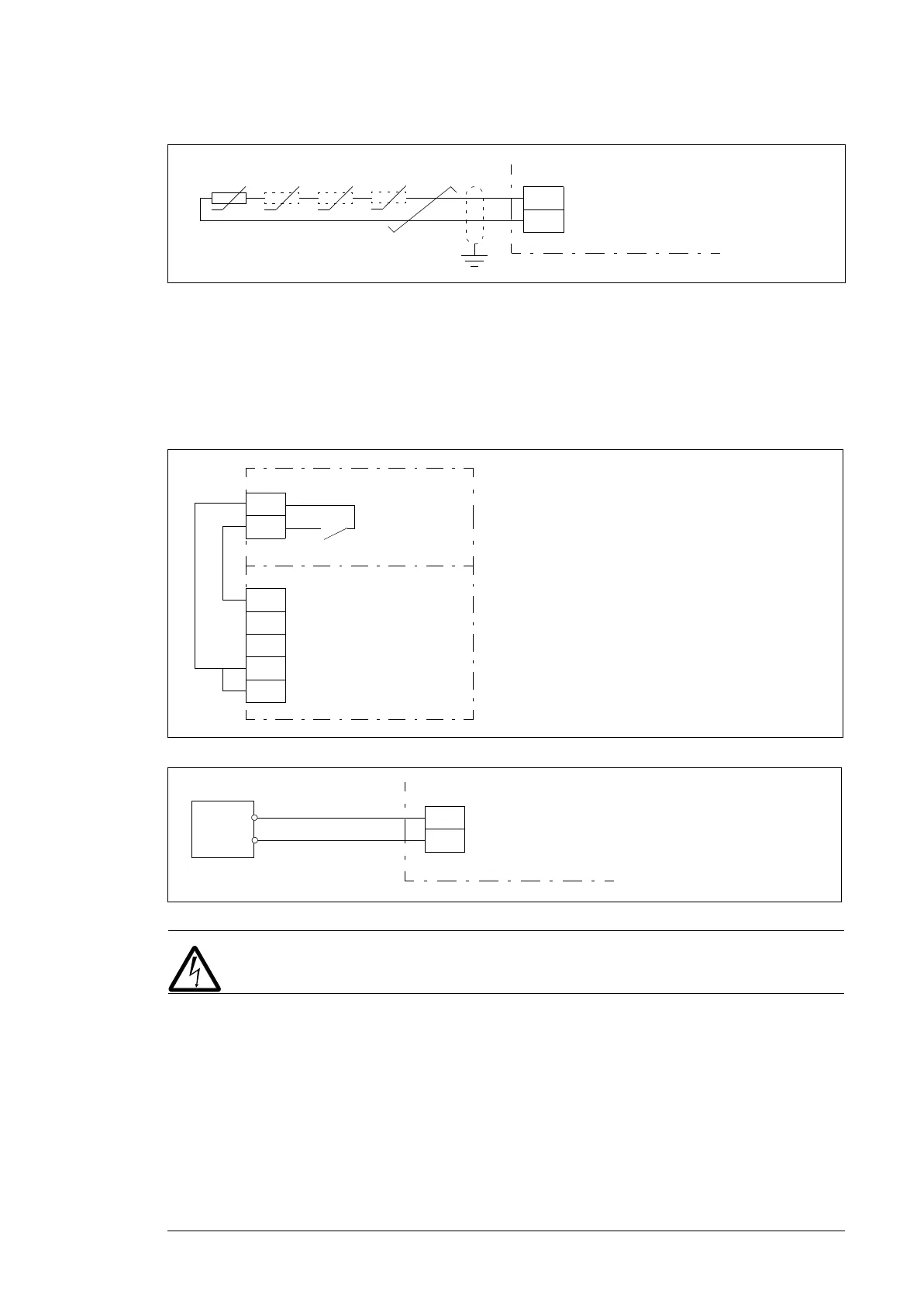
Motor thermistor connection example
1) One or 3…6 PTC thermistors connected in series.
The PTC input is reinforced/double insulated. If the motor part of the PTC sensor and
wiring are reinforced/double insulated, voltages on the PTC wiring are within SELV limits.
If the motor PTC circuit is not reinforced/double insulated (ie, it is basic insulated), it is
mandatory to use reinforced/double insulated wiring between the motor PTC and CMOD-
02 PTC terminal.
Relay output connection example
Power supply connection example
1) External power supply, 24 V AC/DC
WARNING! Do not connect the +24 V AC cable to the control unit ground when
the control unit is powered using an external 24 V AC supply.
Start-up
Setting the parameters
1. Power up the drive.
2. If no warning is shown,
• make sure that the value of both parameter 15.02 Detected extension module and
parameter 15.01 Extension module type is CMOD-02.
60
61
1)
CMOD-02
PTC IN
PTC IN
62
63
CMOD-02
CCU
34
35
X4
36
37
38
OUT1
OUT2
SGND
IN1
IN2
RO PTC C
RO
PTC B
40
41
1)
+
-
24V AC/DC + in
24V AC/DC - in
CMOD-02

 Loading...


