40 Guidelines for planning the cabinet installation
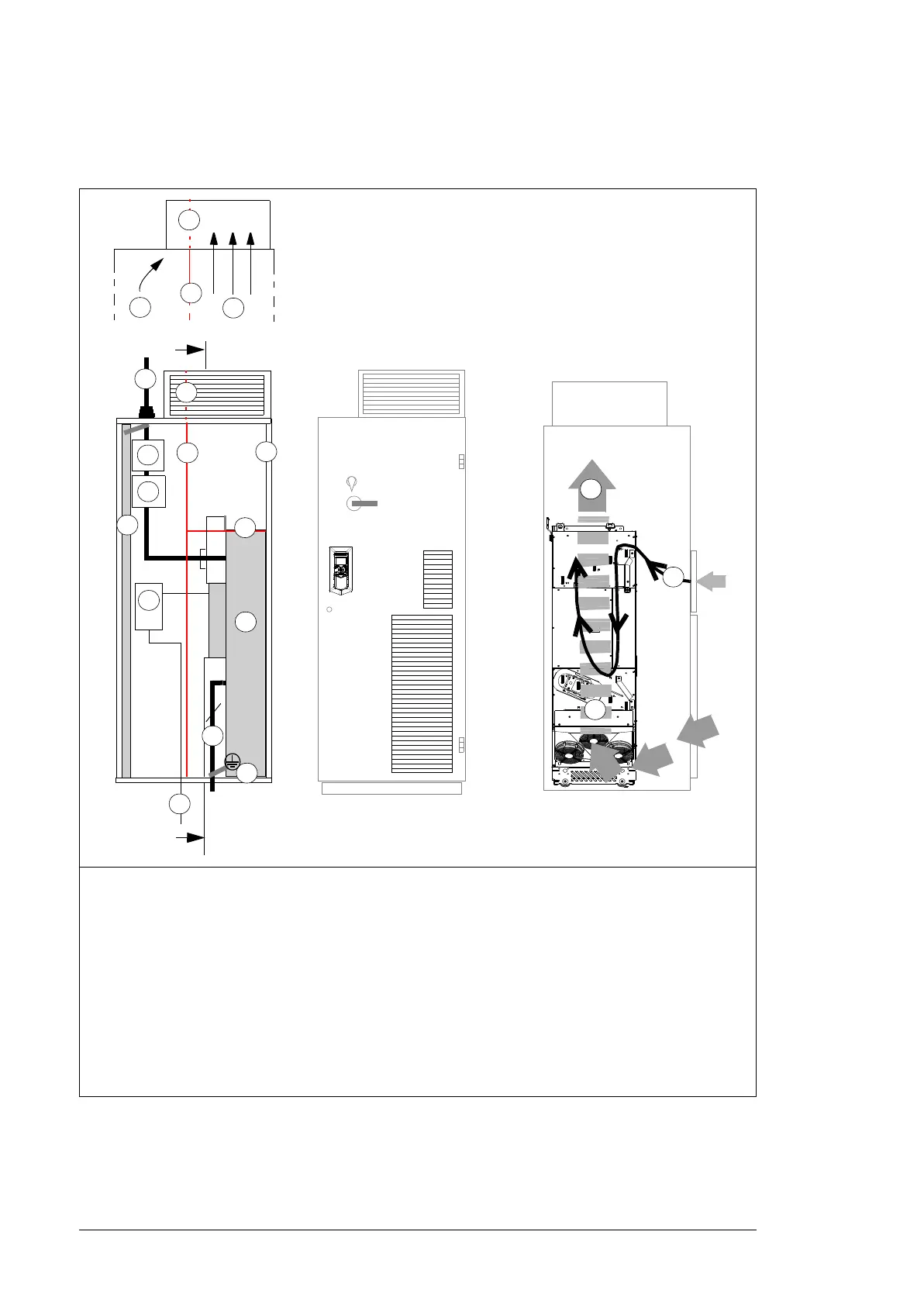
Layout example, door open (option +B051)
This diagram shows a layout example for drive modules with IP20 shrouds (option +B051).
1 Supporting frame of the cabinet 7 Drive module
2a
2b
Vertical (2a) and horizontal (2b) air baffles
that separate the cool and hot areas (leak-
proof lead-throughs). See also page 45.
8 Motor cable including the protective ground conductor
of the drive module
2c Optional air baffle that is needed when there
is no fan on the lower part of the cabinet
door (see 1b on page on 38)
9 Drive module control unit. Note: With an internal control
unit, the upper door air inlet is critical for proper cooling
of the control board.
3 Cabinet grounding busbar (PE) 10 External control cables
4 Input power cable including the protective 11 Grounding screws
ground conductor (PE) of the drive 12 Air flow to the roof
5 Disconnector and fuses 13 Air flow through the drive module
6 Contactor 14 Air flow through circuit boards and to DC output busbars
PE
T3/W2
T2/V2
T1/U2
1
4
5
6
7
3
2a
2a
13
9
10
2c
2e
L1/U1
L2/V1
L3/W1
2b
13
11
A
A
3
8
A – A
14
12
13

 Loading...


