38 Guidelines for planning the cabinet installation
Planning the layout of the cabinet
Plan a spacious layout to ensure easy installation and maintenance. Sufficient cooling air
flow, obligatory clearances, cables and cable support structures all require space.
Place the control board(s) away from:
• main circuit components such as contactors, switches and power cables
• hot parts (heat sink, air outlet of the drive module).
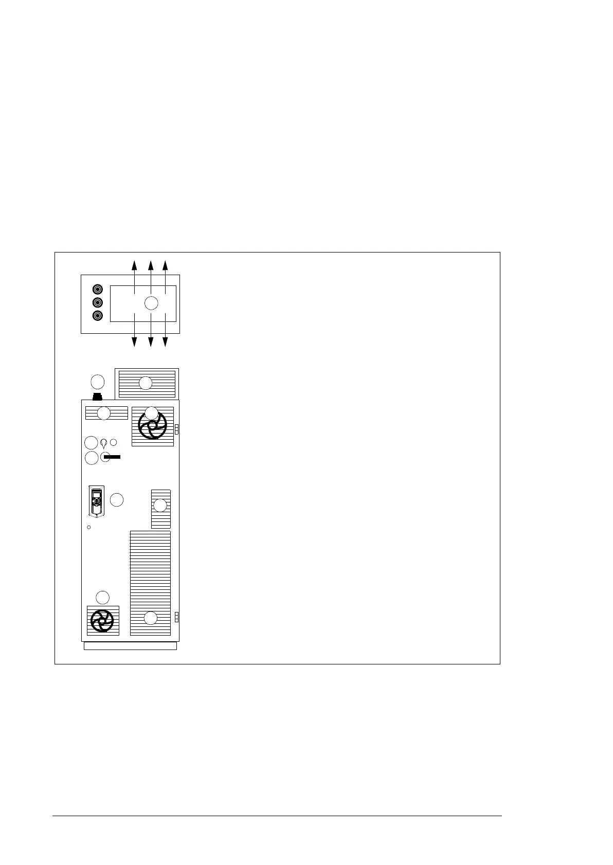
Layout example, door closed
This diagram shows a cabinet layout example with the input power cable lead-through
from top and the motor cable lead-through from bottom.
1a
4
3
2a2b
5
6
1a*
)
Air inlet for the drive module
1b Air inlet for the other equipment. An extra fan is not necessary if an
extra air baffle is used on the cabinet roof (see page 39).
1c*
)
Air inlet for circuit boards and DC and output busbars
2a*
)
Air outlet with an extra exhaust fan for the drive module
2b*
)
Air outlet for the other equipment
2c*
)
Air outlet for the drive module and other equipment on the cabinet
roof. An exhaust fan if needed. We recommend this alternative
instead of 2a.
3 Drive control panel with DPMP-03 mounting platform (option
+J410). The control panel is connected to the drive module control
unit inside the cabinet.
4 Contactor control switch and emergency stop switch (connected to
the contactor control circuit inside the cabinet)
5 Operating handle of the disconnector
6 Rubber grommets for degree of protection
7 Roof air flow viewed from top
*
)
Note: The sizes of the air inlet and outlet gratings are critical for
proper cooling of the drive module. For losses and cooling data
requirements, see page 118.
7
1c
1b
2c

 Loading...


