28 Operation principle and hardware description
Layout
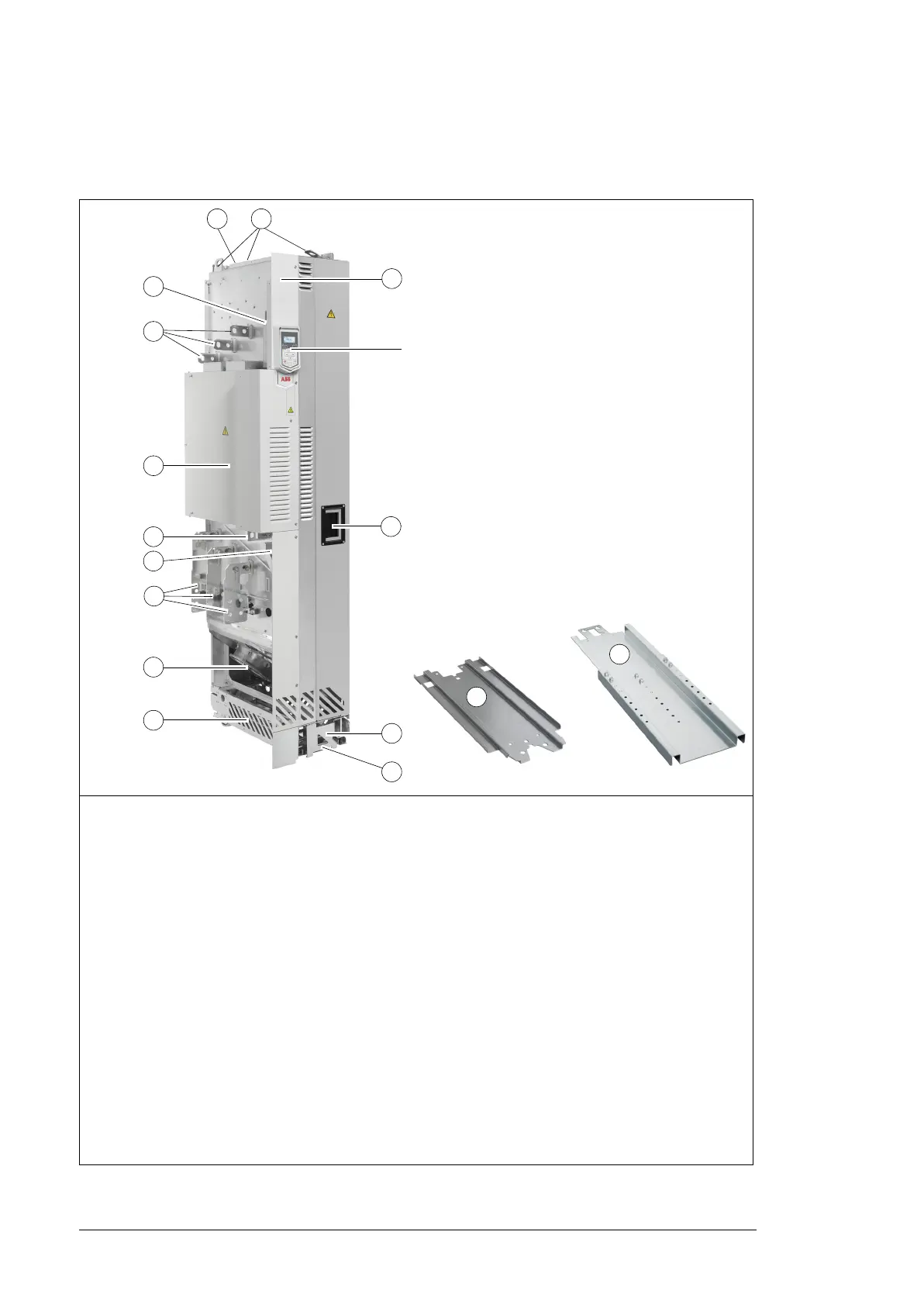
Standard drive module configuration
1 Lifting lugs
2 Fastening bracket
3 Input cable connection busbars (L1/U1, L2/V1, L3/W1)
4 Circuit board compartment
5 PE busbar
6 Output cable connection terminals (T1/U2, T2/V2, T3/W2) attached
7 Control cable duct
8 Main cooling fans
9 Pedestal
10 Upper front cover
11 Lower front cover
12 Control panel. Can also be mounted on the cabinet door as well with the door mounting platform kit.
13 Handle for pulling the drive module out of the cabinet
14 Retractable support legs
15 Base fastening screws behind the retractable support legs
16 Pedestal guide plate
17 Telescopic extraction and insertion ramp

 Loading...


