II F 2-13
3ADW000072R0501_DCS600_System_description_e_e
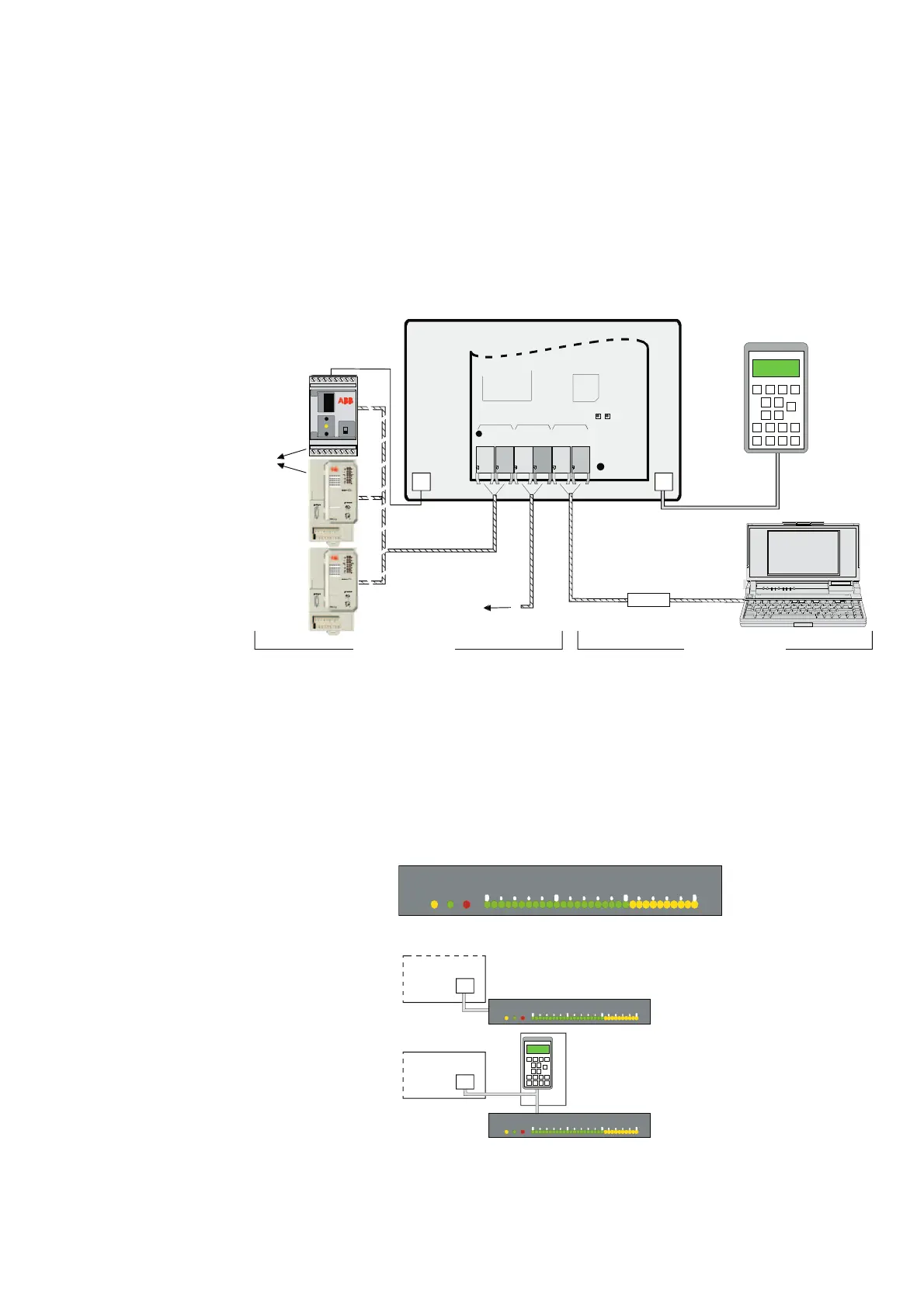
There are various serial interface options available for
operation, commissioning, diagnosis and controlling.
For the control and display panel CDP 312 are serial
connections X33:/X34: on the SDCS-CON-2 availa-
ble. Three additional serial interfaces are available on
the SDCS-AMC-DC 2 board.
These interfaces use plastic or HCS optical fibres.
Channel 3 is used for drive/PC interfacing. Channel 0
for fieldbus module interfacing or communication to
the overriding control system. Channel 2 is used for
Master-Follower link or for I/O extension. All three
serial interfaces are independent from each other.
Fig. 2.5/5: Options for serial communication
Different SDCS-AMC 2 boards are available to adapt
optical cables, cable length and serial interfaces. The
different SDCS-AMC 2 boards are equipped with 10
or 5 Mbaud optical transmitter and receiver devices.
A few basic rules must be considered:
• Never connect 5 Mbaud and 10 Mbaud devices.
• 5 Mbaud can handle only plastic fibre optic.
• 10 Mbaud can handle plastic or HCS cable.
• The branching unit NDBU 95 extends the maxi-
mum distance.
• The maximum distance and suitable configuration
can be found in the manual Configuration Instruc-
tions NDBU 85/95; Doc no.: 3ADW000100.
Fig. 2.5/6: LED Monitoring Display
LED Monitoring Display
If the MultiDrive door Mounting kit is used it is
possible to insert up to three LED monitoring displays
for indicating status as run, ready and fault and a
selectable parameter indicator (0...150%) per drive.
The display is connected to the SDCS-CON-2 board
(X33:/X34:) or to the panel socket NDPI through a
universal Modbus link.
R
D
Y
R
U
N
F
L
T
050100150
1
Remark:
Fieldbus modules Nxxx
(CH0) require the
SDCS-AMC-DC
Classic 2
board - all others (FCI,
AC80...) require the
SDCS-AMC-DC 2 board.
Fig. 2.5/7: Connection of the LED Monitoring Display
Serial interfaces
Operation by panel
Panel location
There are different possibilities for mounting the panel:
• On the converter module.
• With MultiDrive door mounting kit.
X33:/
X34:
SDCS-CON-2
R
D
Y
R
U
N
F
L
T
050100150
1
NLMD
SDCS-CON-2
NDPI
NLMD
R
D
Y
R
U
N
F
L
T
050100150
1
CDP 312
X33:/
X34:
X16:
PC
≤
3 m
CDP 312
D200
CH 3
TxD
RxD
CH 2
TxD
RxD
CH 0
TxD
RxD
D400
SDCS-AMC-DC 2
SDCS-AMC-DC Classic 2
AC800M
FCI
AC80
Nxxx
Nxxx-01
xxxxxxxx
ADAPTER
BUS
TE RM INAT ION
ON
OFF
RXD
TXD
PE SHF DG D(N) D( P)
X1
X2
PE SHF DG D(N) D( P)SH
XMIT
REC
ERROR
+24V 0V SH
X33:
X34:
SDCS-CON-2
Dcs6_com1b.dsf
electrical
connection
optical fibre
Power supply
Control Operation
- Master-Follower link
to the PLC
Interface

 Loading...


