II F 4-1
3ADW000072R0501_DCS600_System_description_e_e
4 Connection examples
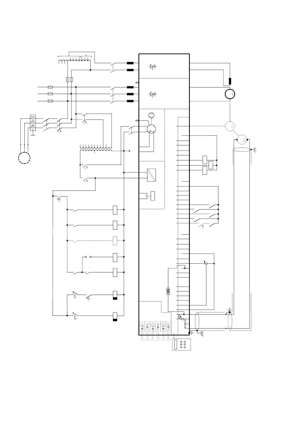
Fig. 4.1/1: DCS 600 Armature current converter wiring diagram
4.1 Armature current converter DCS 600
CH 0
X96:
DO8
12 X99:12 X2:45 X2:1 2 3
U1 W1V1 PE
X1: 1 7
K3 K1
L1 L2 L3
400V 50Hz
F1
F3
K1
135
246
K3
13
24
L1
L3
M
~
T3
F2
1
2
3
4
F6
2
1
4
3
6
5
2
1
4
3
6
5
2
1
4
3
6
5
U
V
W
M
3~
K6
F7
1
2
3
4
K5
F4 F5
1
2
1
2
T2
1
11
10
9
8
7
6
5
4
3
2
690V
660V
600V
575V
525V
500V
450V
415V
400V
380V
12
13
14
115V
230V
K16
K16
K11
F6
K6 K5
X2:4
X2:5
K10
500V
460V
415V
400V
365V
350V
265V
250V
90V
60V
30V
8
7
6
5
4
3
2
1
12
11
10
9
X33
PANEL
CDP 312
C 1 D 1 X1: 5 3
AITAC AI1
AI2 AI3
AI4
+10V -10V AO1 AO2 IACT DI1 DI2 DI3 DI4 DI5 DI6 DI7 DI8 +48V DO1 DO2 DO3 DO4 DO5 DO6 DO7
__ __
_
++++
+
T
T
M
0V
0V0V0V0V
X3:12345678910X4:12345678 910 X6:12345678910 X7:12345678 1...10
X5:
+
_
+
_
+
_
K1
K6
K5
K11
K10
S4
56
K15
K12
*
[K13]
K13
K12
CH 2
CH 3
K12
K15
K16
K15
DCS 600
AMC-DC 2
Control board (CON-2)
Power supply
(POW-1)
Converter
module
ELECTR.
DISCON-
NECT
EMER.
STOP
Field exciter
unit (FEX-1/2)
depending on the unit type (C1, C2, A5, C4)
the polarities are shown for motoring
if there are intermediate terminals
e.g. Pressure
switch at C4
module
* if contactor relay
K13 is used
If SDCS-IOB-2
is in use K10,
K11 and K12
are not
necessary

 Loading...


