II F 2-4
3ADW000072R0501_DCS600_System_description_e_e
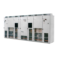
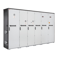
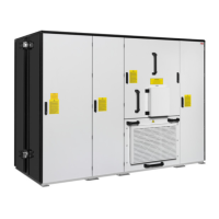
2.2 DCS 600 Power Converter Modules
The power converter modules are modular in construc-
tion. They are based on the housing, which contains the
power section with the RC snubber circuit. There are
different sizes, depending on current and voltage. All
units are forced cooled.
The power section is controlled by the unit’s electronic
system, which is identical for the entire product range.
Parts of the unit’s electronic system can be installed in
the unit, depending on the particular application in-
volved, e.g. a field supply for the motor, or an interface
board to connect the converter to an overriding control
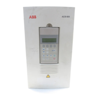
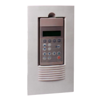
system. A control/display panel is available for the
operator. It can be mounted to the power converter
module or installed in the cabinet's door by means of a
mounting kit.
Accessories such as external fuses, line reactors and the
like are available, for putting together a complete drive
system.
Reference variables
The voltage characteristics are shown
in Table 2.2/1. The DC voltage char-
acteristics have been calculated using
the following assumptions:
• U
VN
= rated mains voltage, 3-phase
• Voltage tolerance ±10 %
• Internal voltage drop approx. 1%
• If a deviation or a voltage drop has
to be taken into consideration in
compliance with IEC and VDE
standards, the output voltage or
the output current must be re-
duced by the actual factor accord-
ing to table 2.2/1.
Table 2.2/1: DCS 600 max. DC voltages achievable with a specified input
voltage.
System con- DC voltage Ideal DC Recommended
nection voltage (recommended) voltage DCS 500B
U
VN
U
dmax 2-Q
U
dmax 4-Q
without load Voltage class
U
di0
y=
230 265 240 310 4
380 440 395 510 4
400 465 415 540 4
415 480 430 560 4
440 510 455 590 5
460 530 480 620 5
480 555 500 640 5
500 580 520 670 5
525 610 545 700 6
575 670 600 770 6
600 700 625 810 6
660 765 685 890 7
690 800 720 930 7
790 915 820 1060 8
1000 1160 1040 1350 9
1190 1380 1235 1590 1
Table 2.2/2: Maximum permitted armature voltage
Max. permitted armature voltage depending on
Field exciter type
Application Armature converter
SDCS-FEX-1 SDCS-FEX-2A
DCF 503A/504A
DCF 501B
DCF 504A
DCF 502B
Power always positive (U
a
and
I
a
pos.).
Extruder
2-Q
U
dmax 2-Q
U
dmax 2-Q
-
Power often or always negative.
Unwinder, suspended load
2-Q
U
dmax 4-Q
U
dmax 4-Q
U
dmax 4-Q
Power sporadically negative.
Printing machine at electrical stop
2-Q - -
U
dmax 2-Q
+
change
software
parameter
Power positive or negative.
Test rig
4-Q
U
dmax 4-Q
U
dmax 4-Q
-
Power positive, sporadically negative.
4-Q
U
dmax 4-Q
U
dmax 2-Q
+
change
software
parameter
-
If armature voltages higher than recommended are re-
quested, please check carefully, wether your system is still
working under safe conditions.
 Loading...
