II F 2-17
3ADW000072R0501_DCS600_System_description_e_e
2.6 Options
Line reactors
for armature (DCS 60x) and field
(DCF 60x) supply
When thyristor power converters operate, the line
voltage is short-circuited during commutation from
one thyristor to the next. This operation causes voltage
dips in the mains. For the connection of a power
converter system to the mains, a decision is made
between the following configurations:
With reference to the power converter:
The line reactors listed in table (2.6/1)
- have been allocated to the units nominal current
- are independent of converter's voltage classifica-
tion; at some converter types the same line choke
is used up to 690 V line voltage
- are based on a duty cycle
- can be used for DCS 600 as well as for DCF 600
converters
Connecting
point
Line
u
k LR
ca. 1%
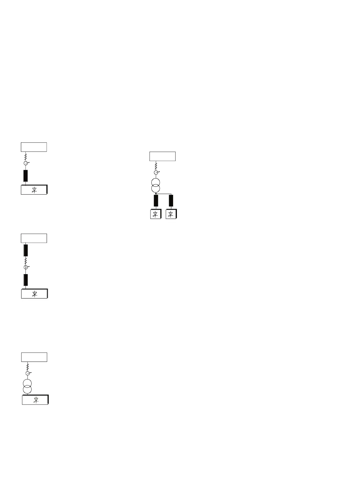
Configuration A
When using the power converter, a
minimum of impedance is required to
ensure proper performance of the snub-
ber circuit. A line reactor can be used to
meet this minimum impedance require-
ment. The value must therefore not
drop below 1% u
k
(relative impedance
voltage). It should not exceed 10% u
k
, due to consider-
able voltage drops which would then occur.
Connecting
point
Line
L
Line
L
LR
Configuration B
If special requirements have to be met at
the connecting point, different criteria
must be applied for selecting a line
reactor. These requirements are often
defined as a voltage dip in percent of the
nominal supply voltage.
The combined impedance of Z
Line
and
Z
LR
constitute the total series imped-
ance of the installation. The ratio be-
tween the line impedance and the line reactor imped-
ance determines the voltage dip at the connecting
point. In such cases line chokes with an impedance
around 4% are often used.
Configuration C
If an isolation transformer is used, it is
possible to comply with certain con-
necting conditions per Configuration
B without using an additional line reac-
tor. The condition described in Con-
figuration A will then likewise be satis-
fied, since the u
k
is >1 %.
Connecting
point
Line
Configuration C1
If 2 or more converters should be sup-
plied by one transformer the final con-
figuration depends on the number of
drives in use and their power capability.
Configuration A or B has to be used
which are based on commutation
chokes, if the drive system consists of
C1, C2 or A5 converters. In case only
two converters type A6 / A7 (A6 + A6,
A6 + A7, A7 + A7) are involved no
commutation chokes are necessary because the design
of these converters is adapted to that wiring.
Line
Connecting
point
L
LR
L
LR
You will find further information in publication:
Technical Guide chapter: Line reactors

 Loading...


