II F 3-6
3ADW000072R0501_DCS600_System_description_e_e
3.8 Software diagrams
Introduction
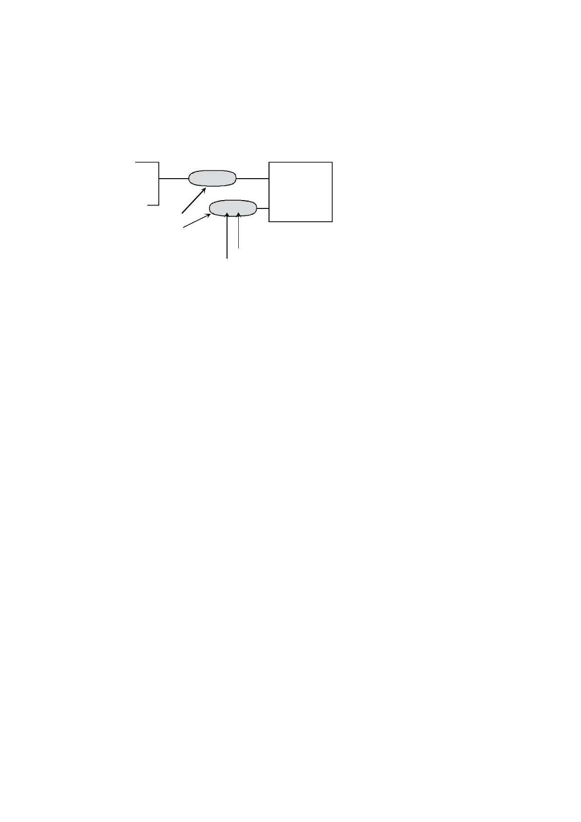
The designation of parameters and signals consist of a
group and a index.
X
Parameter
01.02
23.05
Signal
Group
Index
The structure of the software is given. Changes of the
functions or pointers are realized through setting pa-
rameters.
This can be done via panel, DriveWindow (PC utility),
fieldbus or overriding control system.
Changed parameters or pointers are stored immediate-
ly in the non-volatile flash PROM.
All parameters can be transferred to the PC and be
stored on a data medium by using DriveWindow.
Fig. 3.8/1: Parameter/signal designation
On the following pages the simplified software struc-
ture is shown. Additionally there are specific tables for:
• Main Control Word (MCW)
• Auxiliary Control Words (ACW)
• Main Status Word (MSW)
• Auxiliary Status Word (ASW)
• Digital Inputs (Armature converter mode)
• Digital Inputs (Field converter mode)
• Digital Outputs (Armature converter mode)
• Digital Outputs (Field converter mode)
• Analogue Inputs (Armature converter mode)

 Loading...


