II F 3-1
3ADW000072R0501_DCS600_System_description_e_e
3 Overview of software (Version 15.xxx)
3.1 Basic structure of
DCS 600 MultiDrive
The control hardware of DCS 600 MultiDrive consists
of 2 parts:
• converter control board SDCS-CON-2
• drive control board SDCS-AMC-DC 2
(AMC = Application Motor Control)
Accordingly, the software is split into 2 parts:
• All control functions superimposed to the torque
reference are done inside the AMC board. In addi-
tion, all HMI (Human Machine Interface) and
communication functions are part of the AMC
board's software. Also the Start/Stop functions
('Drive Logic') are realized by the AMC board's
software. All parameters and signals of the drive are
accessed via an on the AMC board residing data
structure called 'AMC-table'.
• All converter related functions and the handling of
standard I/O are done by the SDCS-CON-2 soft-
ware:
• Armature current control
• Field weakening
• Motor protection
• I/O handling
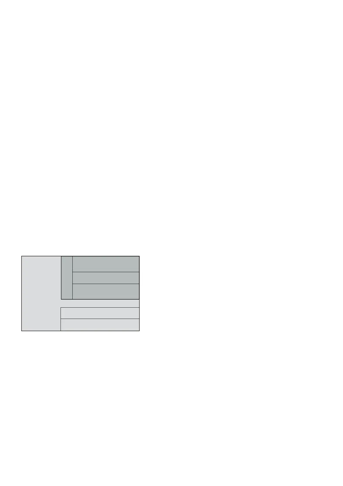
In general, the software functions are distributed be-
tween the SDCS-CON-2 board and the SDCS-AMC-
DC 2 board according to the following diagram:
3.2 Control Modes
The Control mode selects the source of control word
and references.
Local Mode
Commissioning tool DriveWindow is connected to
DDCS channel 3 of the AMC board and can use local
mode. Local mode is also available on the panel CDP
312.
Remote Mode
Reference and control word are supplied by an overrid-
ing control system or a fieldbus adapter connected to
the DDCS channel 0.
Master/Follower Mode
Reference and control word are supplied to the follower
drive by the master drive via DDCS channel 2.
Fig. 3.1/1: Distribution of software functions
Human Machine Interface &
Communication
SDCS-CON-2
Software 15.2xx
Application Control
SDCS-AMC-DC 2
Software 15.6xx
Drive Control
I/O handling
Torque Control

 Loading...


