2.4.3 Securing the base plate
Base plate drawing
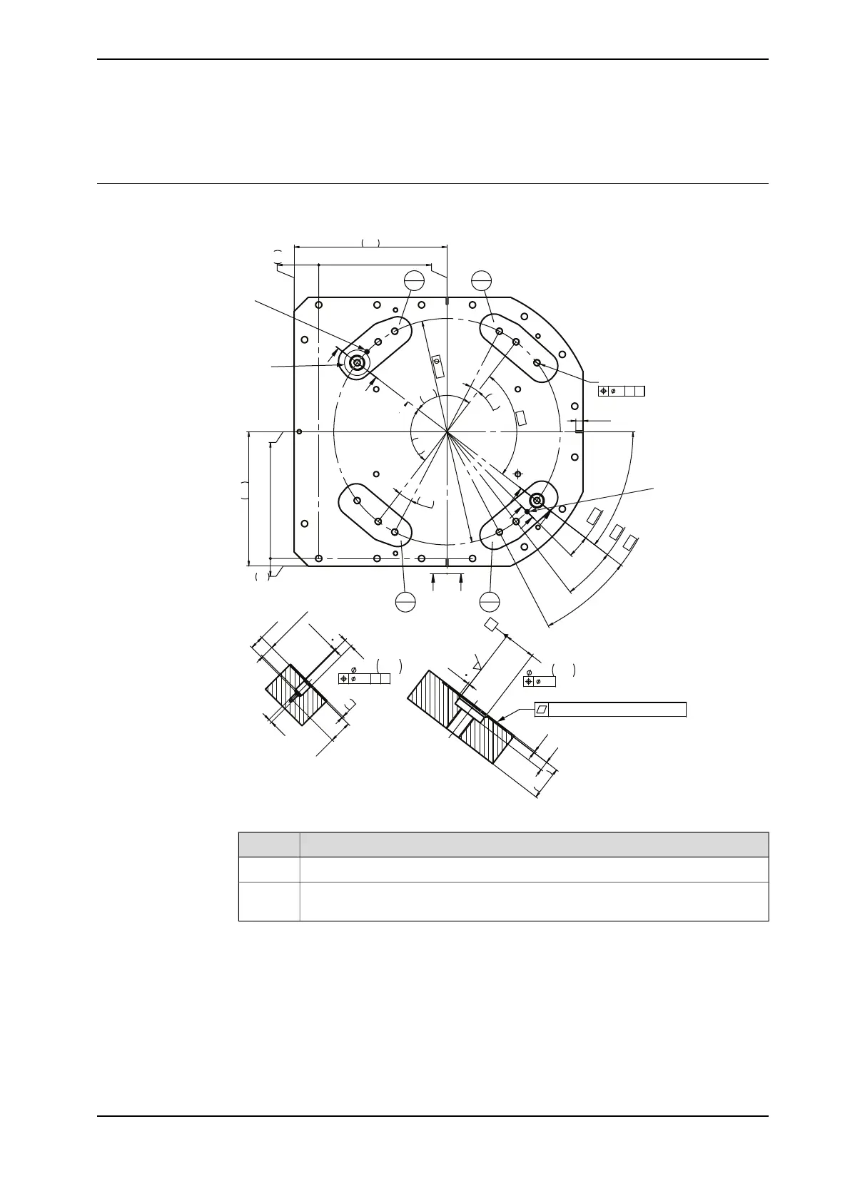
The following figure shows the option base plate (dimensions in mm).
12x M
24
3x
25
4x
1
5°
4x
25°
2x
7,5°
3
7,5°
4x
90°
800
540
475
10°
10°
90°
90°
0
27
448
0
87
453
A
A
B
B
C
C
D
E
E
Ref A-B
E-E
1
A B
H
G
F
E
4x 48
3x45
13
45
P7
-
-
0,017
0,042
A-A
1,6
1,5
A
2x
12
H7
0
+
0,018
2x
1
x45
2x
18
±1
(H7)
20
±1
2
32 ±1
M5
0,1
A B
D
(A)
(B)
0,2
Common Zone E, F, G, H
xx1500000246
DescriptionPos
Hole for guide pin, cylindrical, see Guide pins on page 72A, B
Common tolerance zone (accuracy all over the base plate from one contact
surface to the other)
E, F, G, H
Continues on next page
Product manual - IRB 6700 69
3HAC044266-001 Revision: N
© Copyright 2013 - 2018 ABB. All rights reserved.
2 Installation and commissioning
2.4.3 Securing the base plate
 Loading...