Prepared by, date:
37
We reserve all rights in this document and in the information contained therein.Reproduction, use or
disclosure to third parties without express authority is strictly forbidden. © Copyright 2003 ABB
Page 36
50Total
Latest revision:
Approved by, date:
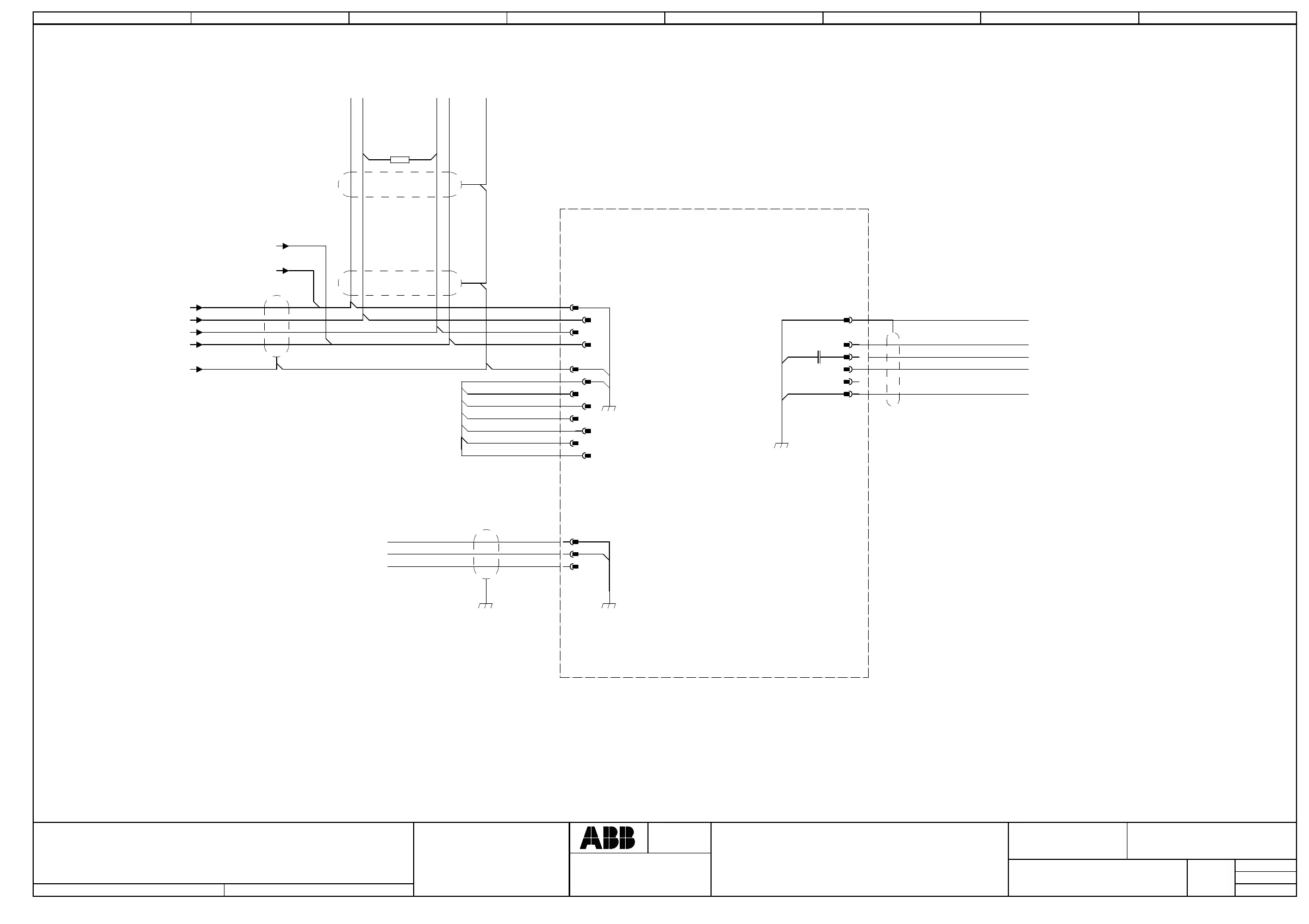
CC-Link
Location:
Plant:
=
+
+
Sublocation:
CAB
Document no.
Next
Rev. Ind
Lab/Office:
Status:
CNYAWU2
11
7 8
3HAC031403-003
Approved
41 2 3 5 6
1) JUMPERS PLACED ACCORDING TO
THE ACTUAL NODE ADDRESS.
2) RESISTANS 120 OHM SHALL ALWAYS
BE CONNECTED IN THE FIRST AND THE
LAST CONNECTOR IN THE CAN-BUS CIRCUIT.
3) CONNECTED IN THE LAST CONNECTOR IN THE
CAN-BUS CIRCUIT.
OR PREVIOUS
I/O UNIT
3)
External supply
2)
0V DC
GND
+24VDC
TO NEXT
I/O UNIT
1)
0V
NA0
NA1
NA2
NA3
NA4
NA5
Customer
Connection
SLD-SHIELD
DA-Signal line A
DG-GND
FG-Power GND
DB-Signal line B
DSQC378B
4
3
2
1
-X8
12
11
-I/Ox.6
CC-Link
12
120 ohm
1
-X3
3
5
1
-X5
2
4
5
3
6
7
8
9
10
5
6
-V- / 22;7
-V+ / 22;7
-DRAIN / 22;7
-CAN_L / 22;7
-CAN_H / 22;7
-+24Vdevicenet.7 /
-0Vdevicenet.7 /

 Loading...