PN25080 Swirlmeter (TRIO-WIRL S) 2 - 7
TRIO-WIRL INSTRUCTION MANUAL
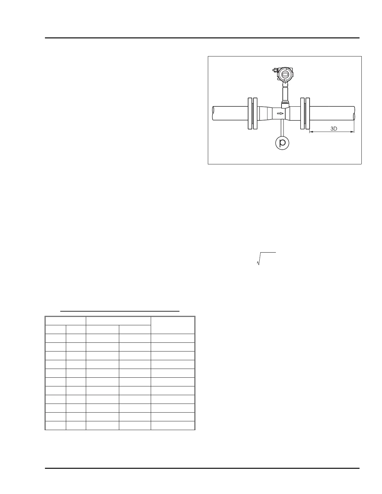
2.4.3 Temperature/Pressure Monitoring
Provisions for temperature and/or pressure monitoring
are the responsibility of the user. The temperature sen-
sor should be located a minimum of three pipe diame-
ters downstream of the flowmeter. Measurement is
from the downstream face of the meter.
An option is available for the Swirlmeter for direct
Pt100 temperature measurements. These temperature
measurements can be used to monitor the fluid tem-
perature or for the measurement of saturated steam in
mass units. The pressure tap is located in the Swirlme-
ter body as shown in Figure 2-9.
2.5 Swirlmeter Size Selection
2.5.1 Gas
The maximum required flowrate should not be less
than 0.5 x Q
VMAX
if possible, but can be set as low as
0.15 Q
VMAX
if required
The flowmeter size selection is made using the maxi-
mum actual volume flowrate (Q
V
), at operating condi-
tions. If the flowrate to be metered is expressed as a
standard flowrate (conditions = 14.7 psia, 70ºF) or as a
mass flowrate, it will be necessary to first convert these
values to their equivalent actual volume flowrate at
operating conditions before selecting the most suitable
flowmeter size from the Flow Range Table below..
2.5.1.1 Q
VMIN
for Gases with ρ < 0.0749 lb/ft
3
The minimum actual volume flowrate Q
VMIN’
for gases
with lower densities can be calculated using the follow-
ing equations.
Q‘
vmin
= Q
vmin
Q
VMIN
Min. volume flowrate from Table 2-1
ρ Density at operating conditions lb/ft
3
1. Convert standard density(ρ
s
) to operating density (ρ)
2. Convert to actual volume flowrate (Q
V
)
a) Starting from standard flowrate (Q
s
) to
b) Starting from mass flowrate (Qm) to Q
v
3. Dynamic Viscosity, µ (cps) to kinematic viscosity, ν(cst)
FIGURE 2-9 MEASURING PRESSURE
TABLE 2-1. SWIRL FLOW RANGES, AIR
Meter Size Flow Range [acfh]
Frequency [Hz]
at Qvmax
Inch DN
Qvmin Qvmax
1/2 15 90 565 1900
1 25 180 1770 1200
1-1/4 32 290 4600 1300
1-1/2 40 430 7070 1400
2 50 640 12370 1200
3 80 2120 30020 690
4 100 2350 52980 700
6 150 5500 127140 470
8 200 8830 173050 330
12 300 18720 353150 160
16 400 37090 706300 150
Air at 70 °F, 14.7 psi, ρ = 0.075 lb/ft
3
0.0749
ρ
----------------
ρρ
s
14.7 p+
14.7
--------------------
×
530
460 T+
-------------------
×=
Q
V
Q
s
14.7
14.7 p+
--------------------
460 T+
530
-------------------
×
ρ
s
ρ
-----
Q
s
×==
Q
V
Q
m
ρ
----------=
ν
µ
ρ
---=

 Loading...