Vortex Meter (TRIO-WIRL V) 3 - 8 PN25080
TRIO-WIRL INSTRUCTION MANUAL
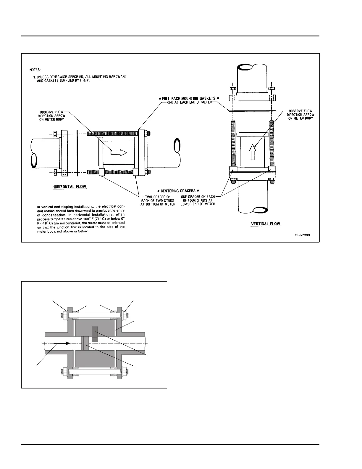
When properly installed, the installation should look like
that shown in Figure 3-7 below.
3.4.2.4 Flanged-Style Installation
Place the two supplied flange gaskets against the
upstream and downstream flange faces (Refer to Table
7-5 for replacement flange gaskets). Align the gasket
holes with the flange hole pattern. When installing the
flange gaskets, make sure that the gaskets fit properly
and are alligned properly so that they don't project into
the pipe line causing an alteration of the flow profile. A
change in flow profile can adversely affect meter accu-
racy.
Mounting bolts and nuts are supplied by the user.
During installation, make certain that the flow direction
arrow on the meter body is oriented in accordance with
the process flow.
With the meter safely supported, install the bolts
through the meter and process flanges. Bolts and nuts
should be lubricated with a graphite based lubricant.
Assemble the nuts to the bolts hand tight. Tighten the
flange nuts in a diagonal or "star" pattern as shown in
Figure 3-8 to equalize pressure on the flange face and
gaskets. Bolt/nut torque should be limited to that which
will provide a leakproof seal.
FIGURE 3-6 WAFER PROCESS CONNECTIONS, SIZES 3 THROUGH 8 INCHES
FIGURE 3-7 WAFER STYLE ASSEMBLY
U-plate
Centering device
or segment
Nut
Gasket
Sensor
Shedder
Flow direction

 Loading...