PN25080 Start-Up & Operation 5 - 3
TRIO-WIRL INSTRUCTION MANUAL
5.2.3 Power Supply Interconnections
5.2.3.1 Power Supplied from a Central Power
Supply
5.2.3.2 Power Supplied from Transmitter Power
Supply
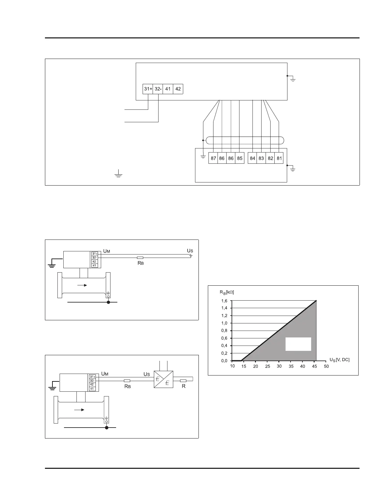
U
M
=Supply voltage TRIO-WIRL = min. 14 V DC
U
S
=Supply voltage, 14 - 46 V DC
R
B
=Max. allow. load for Transmitter Power Supply
(e.g. recorder, cable resistor (refer to Figure 5-8 )
R = Max. allow. load for the output circuit is determined
by the Transmitter Power Supply (e.g. indicator,
recorder, etc.)
5.2.3.3 Hazardous Location Installation
TRIO-WIRL meters are FM/CSA approved for intrinsi-
cally safe & explosion proof operation. Refer to Figure
5-9 for wiring requirements and Figure 5-10 for
labelling.
FIGURE 5-5 INTERCONNECTIONS BETWEEN CONVERTER AND FLOWMETER PRIMARY
Converter
TRIO-WIRL VR/SR
Flowmeter Primary
TRIO-WIRL VR/SR
Supply
Power
Ground
Red
Blue
Pink
Gray
Yello w
Green
Brown
White
FIGURE 5-6 CENTRAL POWER SUPPLY
FIGURE 5-7 TRANSMITTER POWER SUPPLY
Ground
Ground
Ground
Transmitter
Power Sup-
Ground
Allowable
Load
FIGURE 5-8 LOAD DIAGRAM

 Loading...