27
9 ALARM CODES
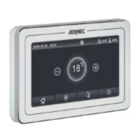
If error or alarm conditions arise during normal operation of the unit, faults will be indicated on the display by icons ( ); it will also be possible to obtain more information
about active errors by checking the specic page in the "View" "Error" page menu (as specied in paragraph "6.3Viewing the status of the unit parameters (Parameter)p.18").
Possible errors (with relative codes) are as follows:
Label Error Description Code
Ambient sensor Indicates a malfunction of the external air sensor F4
Ambient sensor Indicates a malfunction of defrosting temperature sensor on the outdoor unit D6
Discharge sensor Indicates a malfunction of the temperature sensor on compressor delivery F7
Suction sensor Indicates a malfunction of the temperature sensor on compressor intake F5
Econ. in sens. Indicates a malfunction of the temperature sensor at the economizer input F2
Econ. out sens. Indicates a malfunction of the temperature sensor at the economizer output F6
Error fan Indicates a malfunction aecting the fan on the outdoor unit EF
High pressure Indicates abnormal pressure on the high pressure side of the cooling circuit E1
Low pressure Indicates abnormal pressure on the low pressure side of the cooling circuit E3
Hi-discharge Indicates an abnormal temperature on the compressor discharge E4
Capacity DIP Indicates a DIP SWITCH positioning error on the outdoor unit board C5
ODU-IDU Com. Indicates a serial communication error between the AP1 and AP2 cards on the outdoor unit E6
Drive main com Indicates a serial communication error between the AP2 and AP4 cards on the outdoor unit P6
IDU Com. Indicates a serial communication error between the AP1 cards and ush panel (display) E6
HI-pre. sens. Indicates a fault on the high pressure transducer Fc
Temp HELW Indicates a fault on the temperature sensor at heat exchanger plate outlet (water side) F9
Temp AHLW
Indicates a fault on the temperature sensor located downstream of the 3-way valve if the installation includes an auxiliary
electrical resistance or a supplementary heat source
DH
Temp HEEW Indicates a fault on the temperature sensor at heat exchanger plate inlet (water side) -
HI-pre. sens. Indicates a fault on the temperature sensor located on the accessory DHW storage tank FE
T-remote room Indicates a malfunction of the ambient air sensor supplied with the unit F3
HP-Water Switch Indicates an alarm generated by the ow switch at the input to the outdoor unit (water side) Ec
Auxi. heater 1 Indicates a malfunction aecting the auxiliary resistance 1 (KM1) EH
Auxi. heater 2 Indicates a malfunction aecting the auxiliary resistance 2 (KM2) EH
Auxi. WTH Indicates a malfunction aecting the resistance placed in the accessory DHW storage tank (KM3) Eh
DC under vol. Indicates an error caused by low voltage on the DC bus or an error caused by a voltage drop PL
DC over vol. Indicates an error caused by high voltage on the DC bus PH
AC curr. pro. Indicates an abnormal value for AC current (AC protection) PA
IPM defective Indicates an operating fault on the IPM module (inverter power module) H5
PFC defective Indicates an operating fault on the PFC module (power correction module) Hc
Start failure Indicates a fault in the unit’s start-up phase Lc
Phase loss Indicates a problem associated with the loss or unbalance of voltage phases Ld
Com Driver Indicates a communication error with the unit’s drivers P6
Driver reset Indicates a reset made on the unit’s drivers P0
Com. over cur. Indicates that an overcurrent on the compressor has been detected P5
Overspeed Indicates that an incorrect compressor speed has been detected LF
Current sen. Indicates an abnormal value for the current sensor Pc
Desynchronize Indicates that the compressor is out of sync H7
Comp. stalling Indicates that the compressor is currently stalled LE
Overtemp. mod. Indicates that an overtemperature has been detected on a component (heatsink, IPM or PFC) P8
T mod. sensor Indicates that an error has been detected on the temperature sensor for a component (heatsink, IPM or PFC) P7
Charge circuit Indicates an error on the charging circuit Pu
AC voltage Indicates a power supply error PP
Temp driver Indicates an error aecting the external air sensor PF
AC contactor Indicates a protection status on the power supply P9
Temp. drift Indicates a protection status for drift temperature PE
Sensor con. Indicates a protection status for the sensor monitoring the phases Pd
ODU Com. Indicates a serial communication error between the display and the outdoor unit E6
Temp RGL Indicates an error aecting the temperature sensor on the cooling circuit gas line F0
Temp RLL Indicates an error aecting the temperature sensor on the cooling circuit uid line F1
 Loading...