Rockwell Automation Publication 1734-UM001E-EN-P - July 2013
POINT I/O Module Data 103
Data
The1734-IE2C module operates in unipolar mode only; the 1734-IE2V module
operates in unipolar or bipolar modes. Data returned from the module is scaled
by the user to any 16-bit signed integer (–32,768…+32,767). Six bytes of data are
read from the 1734-IE2C and 1734-IE2V modules. No data is written to the
input modules.
• Channel 0 Data (2 bytes)
• Channel 1 Data (2 bytes)
• Channel 0 Status (1 byte)
• Channel 1 Status (1 byte)
Communicate with Your Module
I/O messages are sent to (consumed) and received from (produced) the
POINT I/O modules. These messages are mapped into the processor’s
memory.
(1)
These POINT I/O input modules produces six bytes of input data
(scanner Rx) and fault status data. It does not consume output data (scanner Tx).
(1) These are mapped through scan lists in DeviceNet networks and Direct, Listen Only, or Rack-optimized
connections in ControlNet and EtherNet/IP networks.
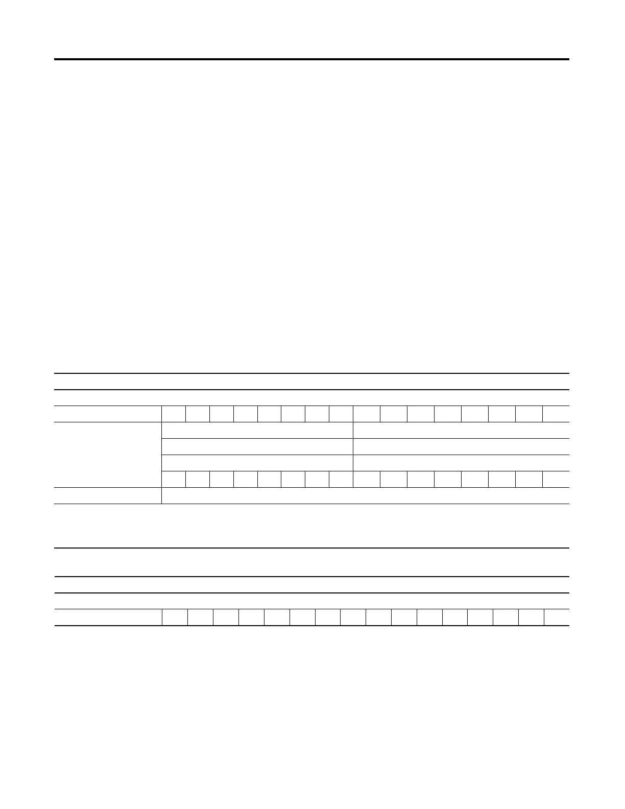
Default Data Map for the 1734-IE2C Analog Input Module
Message Size: 6 Bytes
15 14 13 12 11 10 09 08 07 06 05 04 03 02 01 00
Produces (scanner Rx) Input Channel 0 High Byte Input Channel 0 Low Byte
Input Channel 1 High Byte Input Channel 1 Low Byte
Status Byte for Channel 1 Status Byte for Channel 0
OR UR HHA LLA HA LA CM CF OR UR HHA LLA HA LA CM CF
Consumes (scanner Tx) No consumed data
Where: CF = Channel Fault status; 0 = no error, 1 = fault
LA = Low Alarm; 0 = no error, 1 = fault
LLA = Low/Low Alarm: 0 = no error, 1 = fault
UR = Underrange; 0 = no error, 1 = fault
CM = Calibration Mode; 0 = normal, 1 = calibration mode
HA = High Alarm; 0 = no error, 1 = fault
HHA = High/High Alarm; 0 = no error, 1 = fault
OR = Overrange; 0 = no error, 1 = fault
Default Data Map for the 1734-IE2V Analog Input Module
Message Size: 6 Bytes
15 14 13 12 11 10 09 08 07 06 05 04 03 02 01 00

 Loading...


