Rockwell Automation Publication 1734-UM001E-EN-P - July 2013
174 Default Data Maps
Analog Module Default
Data Maps
I/O messages are sent to (consumed) and received from (produced) the
POINT I/O modules. You map these messages into the processor memory.
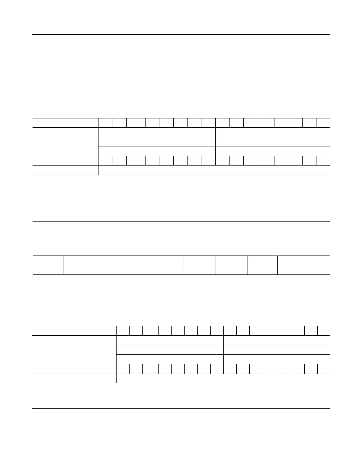
1734-IE2C Analog Current Input Module
Message Size: 6 Bytes
Channel Status
1734-IE2V Analog Voltage Input Module
Message Size: 6 Bytes
15 14 13 12 11 10 09 08 07 06 05 04 03 02 01 00
Produces (scanner Rx) Input Channel 0 High Byte Input Channel 0 Low Byte
Input Channel 1 High Byte Input Channel 1 Low Byte
Status Byte for Channel 1 Status Byte for Channel 0
OR UR HHA LLA HA LA CM CF OR UR HHA LLA HA LA CM CF
Consumes (scanner Tx) No consumed data
Where: CF = Channel Fault status0 = no error1 = fault
CM = Calibration Mode 0 = normal1 = calibration mode
LA = Low Alarm 0 = no error1 = fault
HA = High Alarm 0 = no error1 = fault
LLA = Low/Low Alarm 0 = no error1 = fault
HHA = High/High Alarm 0 = no error1 = fault
UN = Underrange 0 = no error1 = fault
OR = Overrange 0 = no error1 = fault
Channel Status Bytes
Bit 7 Bit 6 Bit 5 Bit 4 Bit 3 Bit 2 Bit 1 Bit 0
Over Range Under Range High High Alarm Low Low Alarm High Alarm Low Alarm CAL Mode Channel Fault
15 14 13 12 11 10 09 08 07 06 05 04 03 02 01 00
Produces (scanner Rx) Input Channel 0 - High Byte Input Channel 0 - Low Byte
Input Channel 1 - High Byte Input Channel 1 - Low Byte
Status Byte for Channel 1 Status Byte for Channel 0
OR UR HHA LLA HA LA CM CF OR UR HHA LLA HA LA CM CF
Consumes (scanner Tx) No consumed data
Where: CF = Channel Fault status; 0 = no error, 1 = fault CM = Calibration Mode; 0 = normal, 1 = calibration mode
LA = Low Alarm; 0 = no error, 1 = fault HA = High Alarm; 0 = no error, 1 = fault
LLA = Low/Low Alarm; 0 = no error, 1 = fault HHA = High/High Alarm; 0 = no error, 1 = fault
UR = Underrange; 0 = no error, 1 = fault OR = Overrange; 0 = no error, 1 = fault

 Loading...


