Rockwell Automation Publication 1734-UM001E-EN-P - July 2013
48 Install POINT I/O Modules
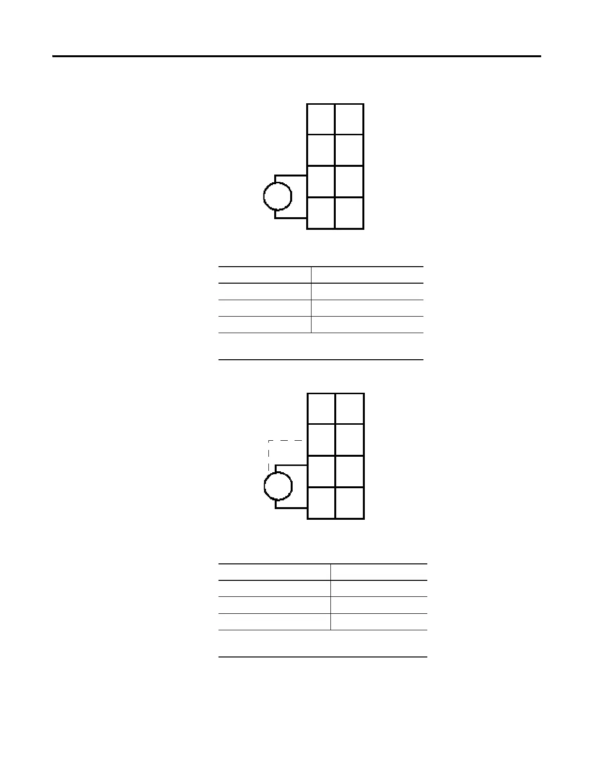
1734-FPD Modules for 12/24V DC Wiring Diagram
1734-FPD Modules for 120/240V AC Wiring Diagram
Create a New AC Power Bus Using a 1734-FPD Module
Connect Terminal
+V DC 6
-V DC 4
Chas Gnd 2
12/24V DC becomes the internal power bus for modules
to the right.
Connect Terminal
L1 6
L2/N 4
Chas Gnd 2
120/240V DC becomes the internal power bus for
modules to the right.
NC NC
C
VV
C
V DC
V = 12/24V DC, C = Common
CHAS GND = Chassis ground
This supply will be
connected to the
internal power bus.
3
5
7
01
2
4
6
CHAS
GND
CHAS
GND
L2/N
L1 L1
L2/N
V AC
L2/N = Neutral, L1 = 120/240V AC
CHAS GND = Chassis ground
NC NC
This supply will be
connected to the
internal power bus.
3
5
7
01
2
4
6
CHAS
GND
CHAS
GND

 Loading...


