Rockwell Automation Publication 1734-UM001E-EN-P - July 2013
Install POINTBlock I/O Modules 93
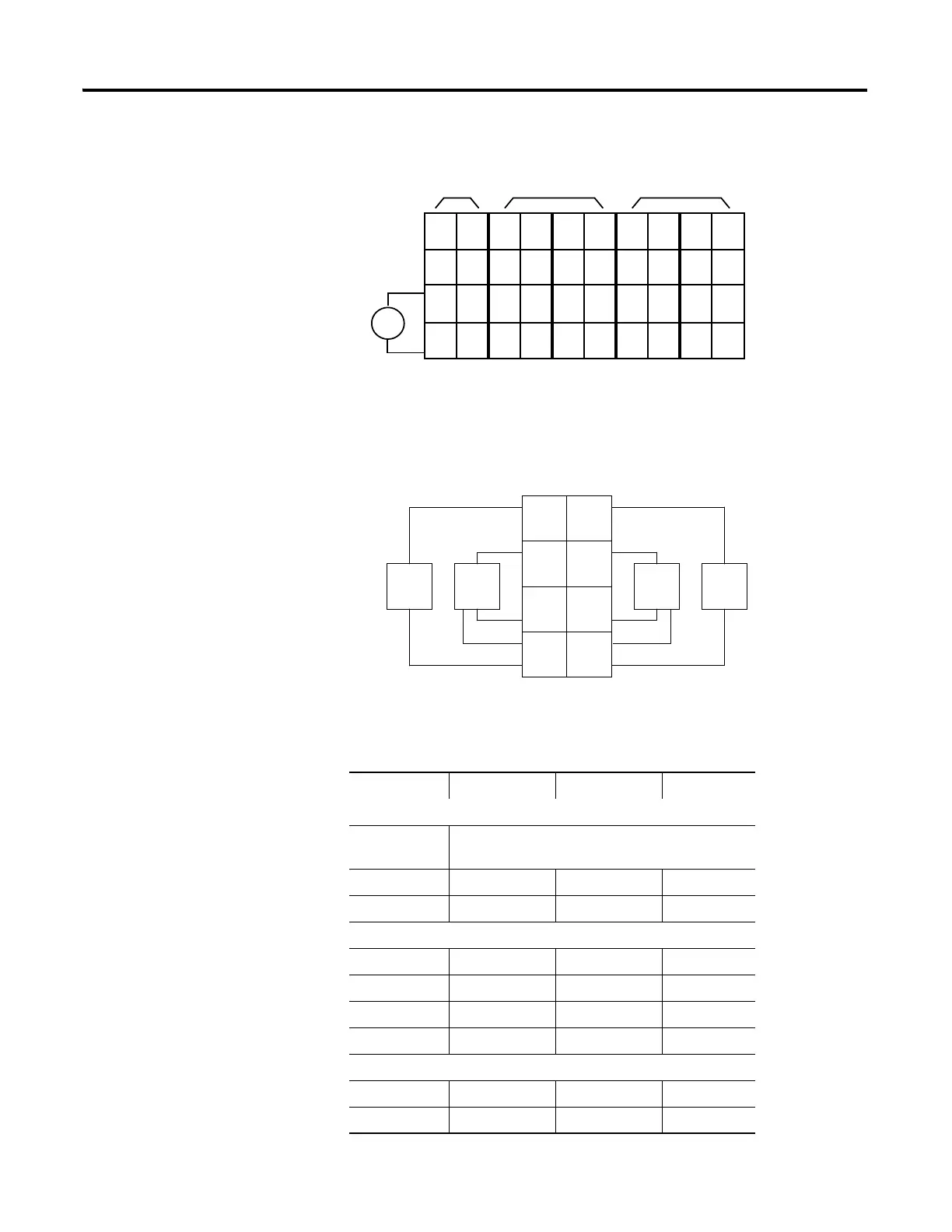
16 DC Input Module Wiring Diagram
Sink Input Wiring Diagram
Channel Input Terminal Common Voltage
Remote Termination Block 0
Field Power
Block
Vin (supply) 6 and 7
Common) 4 and 5
Remote Termination Block 1
0046
1157
2246
3357
Remote Termination Block 2
4046
5157
V dc
NC
NC
Cin
Vin
12/24V dc
NC
NC
Cin
Vin
0
2
C
V
1
3
C
V
4
6
C
V
5
7
C
V
8
10
C
V
9
11
C
V
12
14
C
V
13
15
C
V
Field
Power
Inputs
This supply will be connected to the internal power bus.
01
23
45
67
01
23
45
67
01
23
45
67
01
23
45
67
01
23
45
67
RTB 0 RTB 1 RTB 2 RTB 3 RTB 4
NC =
No Connection
C = Common
Chas Gnd =
Chassis Ground
V = Supply
Prox
In 0 In 1
In 2
C
VV
C
In 3
Prox ProxProx
V = 12/24V dc
C = Common
3
5
7
01
2
4
6
3-wire2-wire
RTB 1
Repeat for RTB 2, RTB 3 and RTB 4.

 Loading...


