Rockwell Automation Publication 1734-UM001E-EN-P - July 2013
Install POINTBlock I/O Modules 91
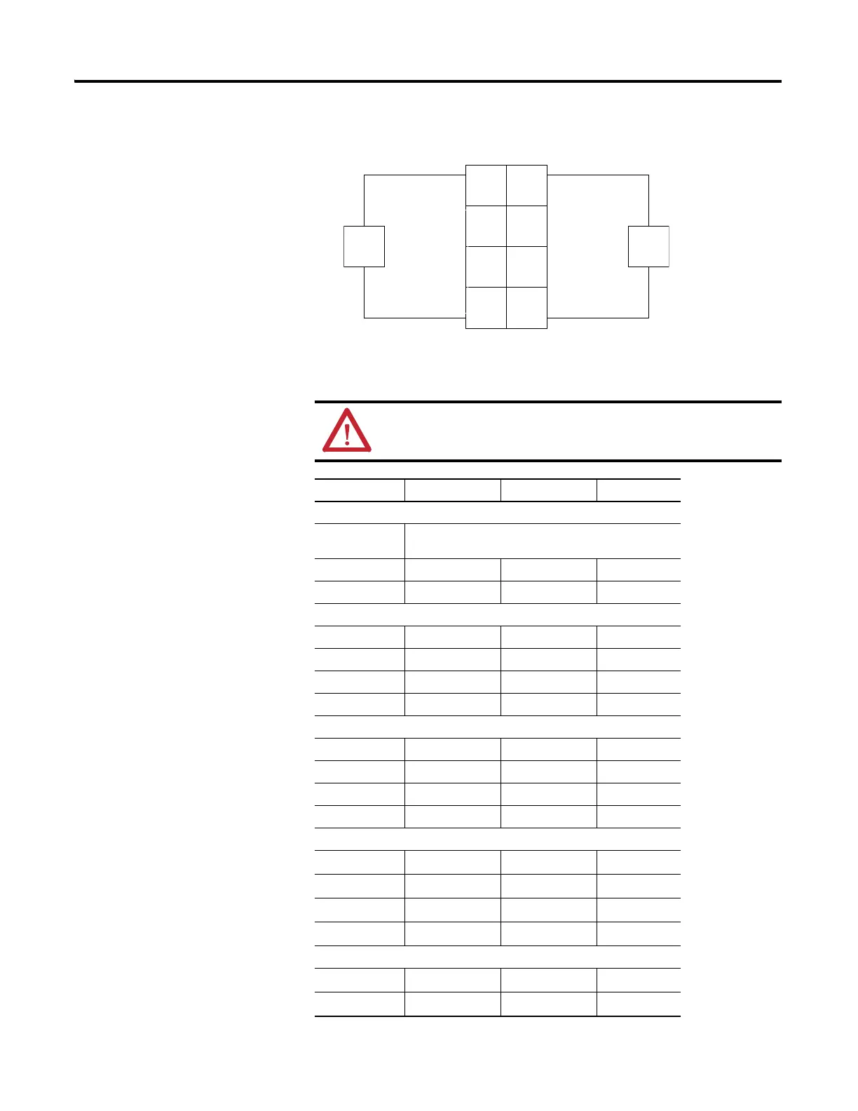
Input Wiring Diagram
ATTENTION: When connecting more than one wire in a
termination point, make sure that both wires are the same gauge
and type.
Channel Input Terminal Return Voltage
Remote Termination Block 0
Field Power
Block
Vin (L1) 6 and/or 7
Return (L2/N) 4 and/or 5
Remote Termination Block 1
00 6
11 7
22 6
33 7
Remote Termination Block 2
40 6
51 7
62 6
73 7
Remote Termination Block 3
80
6
91
7
10 2
6
11 3
7
Remote Termination Block 4
12 0
6
13 1
7
Prox
In 0 In 1
In 2
L2
L1 L1
L2
In 3
Prox
L1 = 120V ac
L2 = Return
3
5
7
01
2
4
6
Repeat for RTB 2, 3 and 4
RTB 1

 Loading...


