Rockwell Automation Publication 1734-UM001E-EN-P - July 2013
Install POINT I/O Modules 53
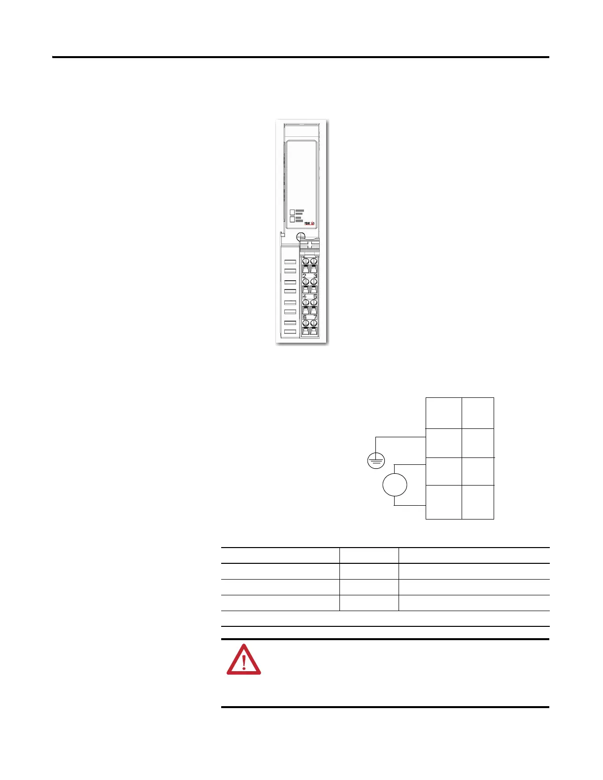
1734-EPAC AC Expansion Power Supply
120/240V AC Wiring Diagram
Connect Terminal Terminals (for continuing power)
L1 (120/240V AC) 6 7
L2/N( Neutral) 4 5
PE (Protective Earth ground) 2 3
120/240V AC becomes the internal power bus for modules to the right.
ATTENTION: If you connect or disconnect wiring while field side power
is on, an electrical arc can occur. This could cause an explosion in
hazardous location installations.
Be sure that power is removed or the area is nonhazardous before
proceeding.
L2/N
L1
NC
L2/N
L1
NC
NC = No Connection
PE = Protective Earth Ground
L2/N = Neutral
L1 = 120/240V AC
PE
PE
NC
PE
L2/N
L1 L1
L2/N
V AC
L1 = 120/240V AC
L2/N = 120/240V AC
PE = Protective Earth Ground
Connect ground wire to
PE terminal.
PE
This AC supply will be
connected to the internal
power bus.
NC
0
2
3
1
4
5
6
7

 Loading...


