Rockwell Automation Publication 1734-UM001E-EN-P - July 2013
Install POINTBlock I/O Modules 89
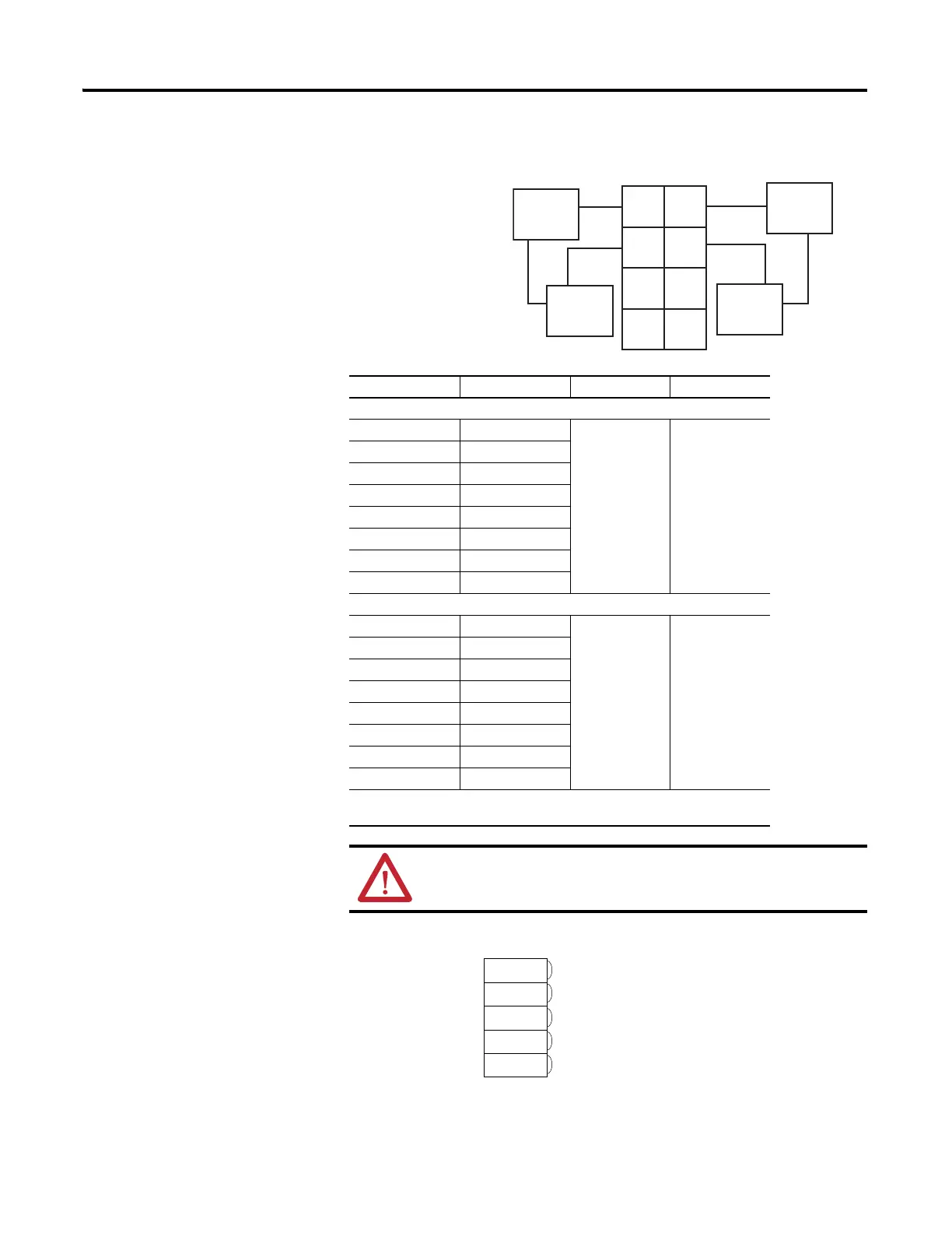
Output Wiring Diagram
DeviceNet Connector Wiring
Channel Output Common Supply
Remote Termination Block 3
0A 0 Not used Not used
0B 2
1A 1
1B 3
2A 4
2B 6
3A 5
3B 7
Remote Termination Block 4
4A 0 Not used Not used
4B 2
5A 1
5B 3
6A 4
6B 6
7A 5
7B 7
Supply voltage is 120V ac.
120V AC power for the module is provided by the internal power bus.
ATTENTION: When connecting more than one wire in a
termination point, make sure that both wires are the same gauge
and type.
Out 0A
Out 0B
Out 1A
Out 1B
Load
Power
Supply
Out = Output channel relay contacts
L1 = 120V ac
L2 = Return
Load Powered by External Power
0
2
4
6
3
5
7
1
Power
Supply
Load
Out 2A
Out 2B
Out 3A
Out 3B
DeviceNet
Connection
Red
White
Bare
Blue
Black
-V
+V
CAN - High
Shield
CAN - Low

 Loading...


