Rockwell Automation Publication 1734-UM001E-EN-P - July 2013
12 Install POINT I/O Modules
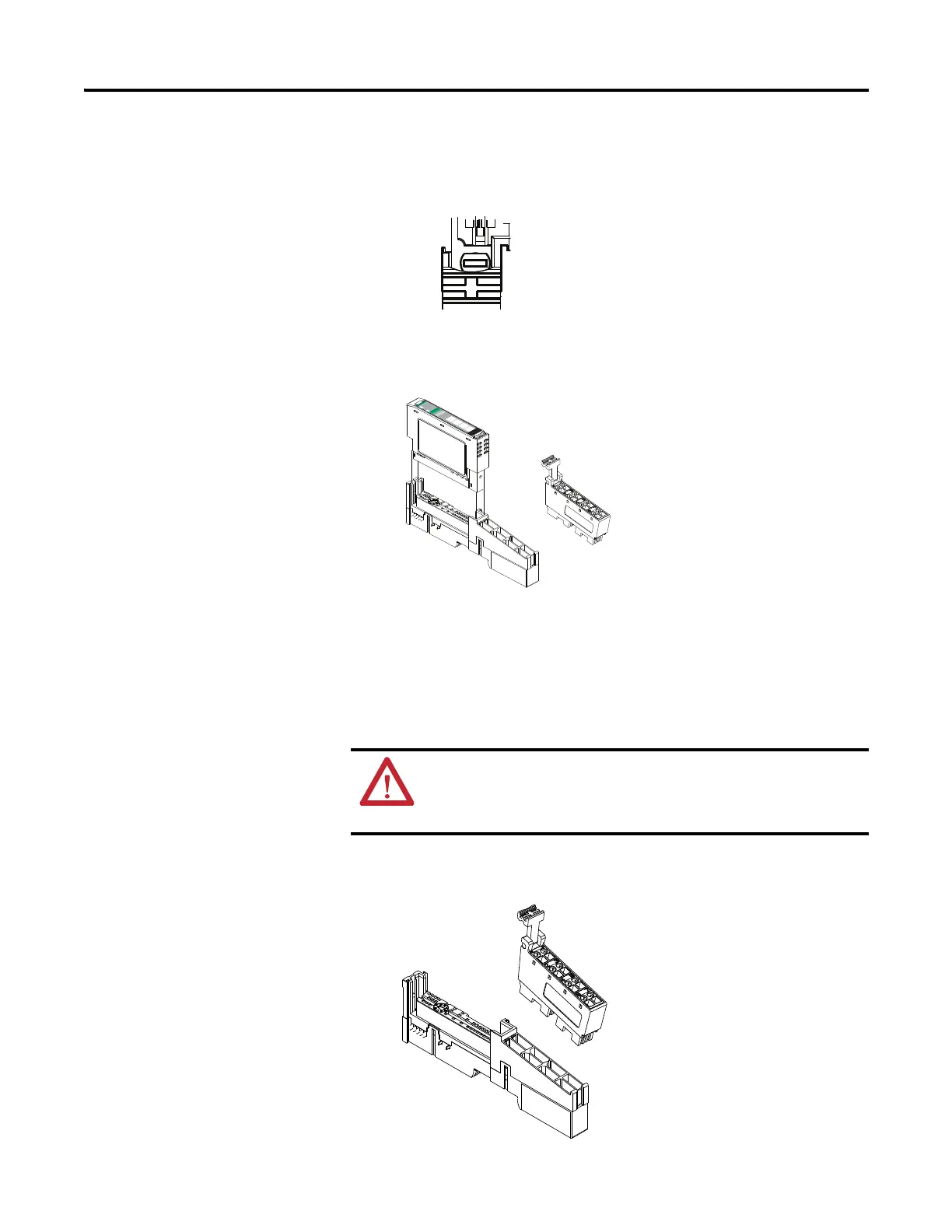
2. Make certain the DIN-rail locking screw is in the horizontal position,
noting that you cannot insert the module if the locking mechanism is
unlocked.
3. Insert the module straight down into the mounting base and press to
secure, locking the module into place.
Install the Removable
Terminal Block
A removable terminal block is supplied with your mounting base assembly. To
remove, pull up on the removable terminal block (RTB) handle. This lets you
remove and replace the base as necessary without removing any of the wiring. To
reinsert the removable terminal block, proceed as follows.
1. Insert the RTB end opposite the handle into the base unit.
This end has a curved section that engages with the mounting base.
24V
D
C
So
u
rce
Outp
u
t
Mo
dule
Status
Netw
or
k
Status
17
3
4
OB4E
NODE:
0
1
2
3
WARNING: When you connect or disconnect the RTB with field-side
power applied, an electrical arc can occur. This could cause an explosion
in hazardous location installations. Be sure to remove power or that the
area is nonhazardous before proceeding.

 Loading...


