Rockwell Automation Publication 1734-UM001E-EN-P - July 2013
32 Install POINT I/O Modules
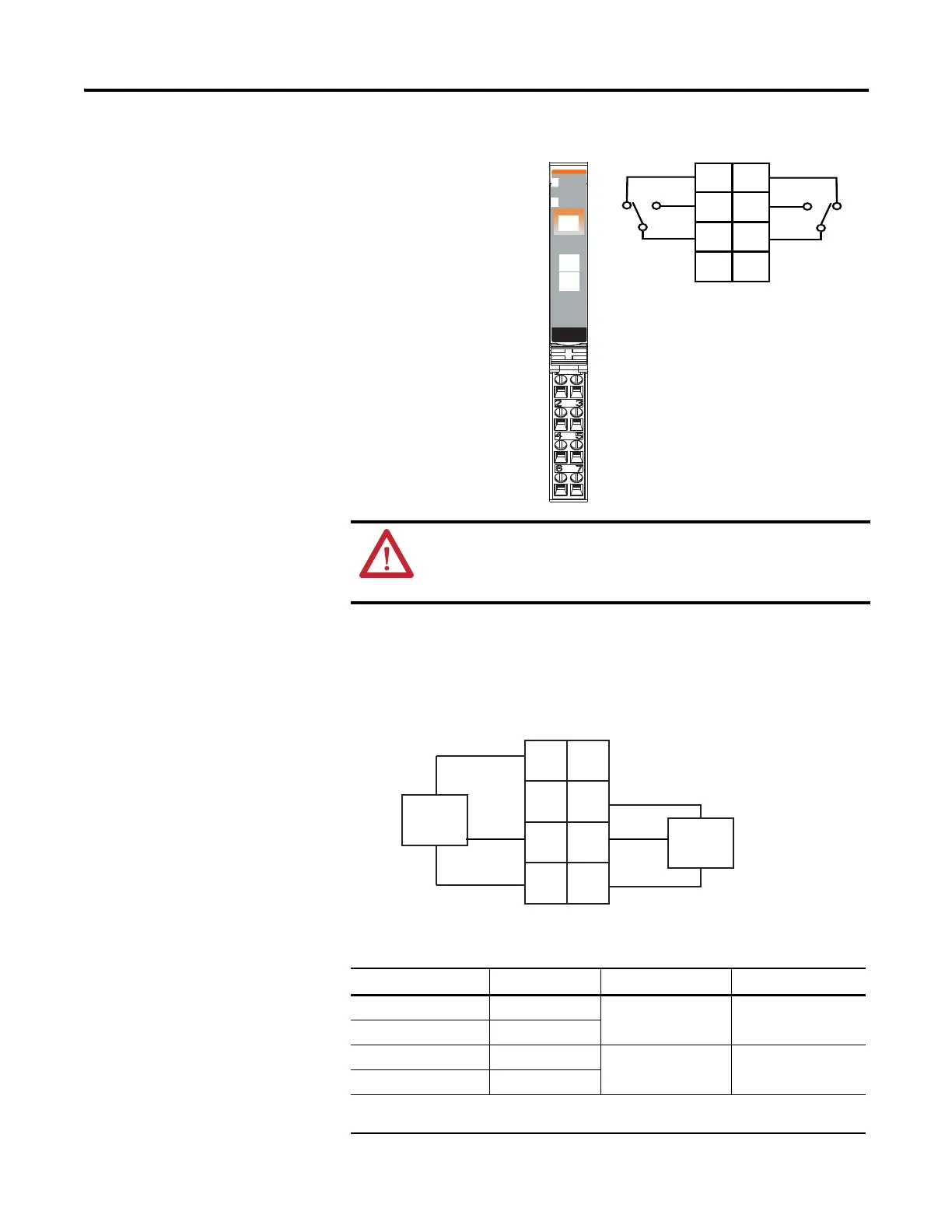
1734-OX2 2-relay Output Modules
1734-OX2 Module with Load Powered by Internal Power Bus
Wiring Diagram
ATTENTION: Relay contacts are not powered by the internal power bus.
Load power can be provided by the internal power bus or an external
power source.
Channel Output Relay Common Supply
0 (N.C.) 0 4 6
0 (N.O.) 2
1 (N.C.) 1 5 7
1 (N.O.) 3
Supply voltage can range from +5V DC…240V AC, depending on relay load.
12V, 24V DC, 120V, 240V AC power for the module is provided by the internal power bus.
Relay
Output
Module
Status
Network
Status
1734
OX2
NODE:
0
1
41974
Module Status
Network Status
Status of Output 0
Status of Output 1
Output 0 Relay Common - RC
+V
RC - Output 1 Relay Common
+V
Output 0 Connection - NC
Output 0 Connection - NO
NC - Output 1 Connection
NO - Output 1 Connection
NC = Normally closed
NO = Normally open
RC = Relay Common
+V = Positive Supply
+V
+V
Out 0
NC
Out 1
NC
Load
Load
0
2
4
6
3
5
7
1
L1
L1
NC = Normally closed
NO = Normally open
RC = Relay Common
+V = Positive Supply
L2/N
L2/N
Out 0
NO
Out 1
NO
Out 0
RC
Out 1
RC

 Loading...


