Rockwell Automation Publication 1734-UM001E-EN-P - July 2013
About the Modules 5
• Low and high clamps can be set individually or on a channel basis. When
the output value reaches clamp value, a status bit is set, indicating the
output is clamped.
• Disable alarms - disables all channel alarms and faults so they are not
reported in the channel status field.
• Fault and Idle mode action let you select what happens to the output if
a fault occurs or if the module is in idle mode. The choices are the
following:
– Hold Last State
– Low Clamp
– High Clamp
– User-defined value
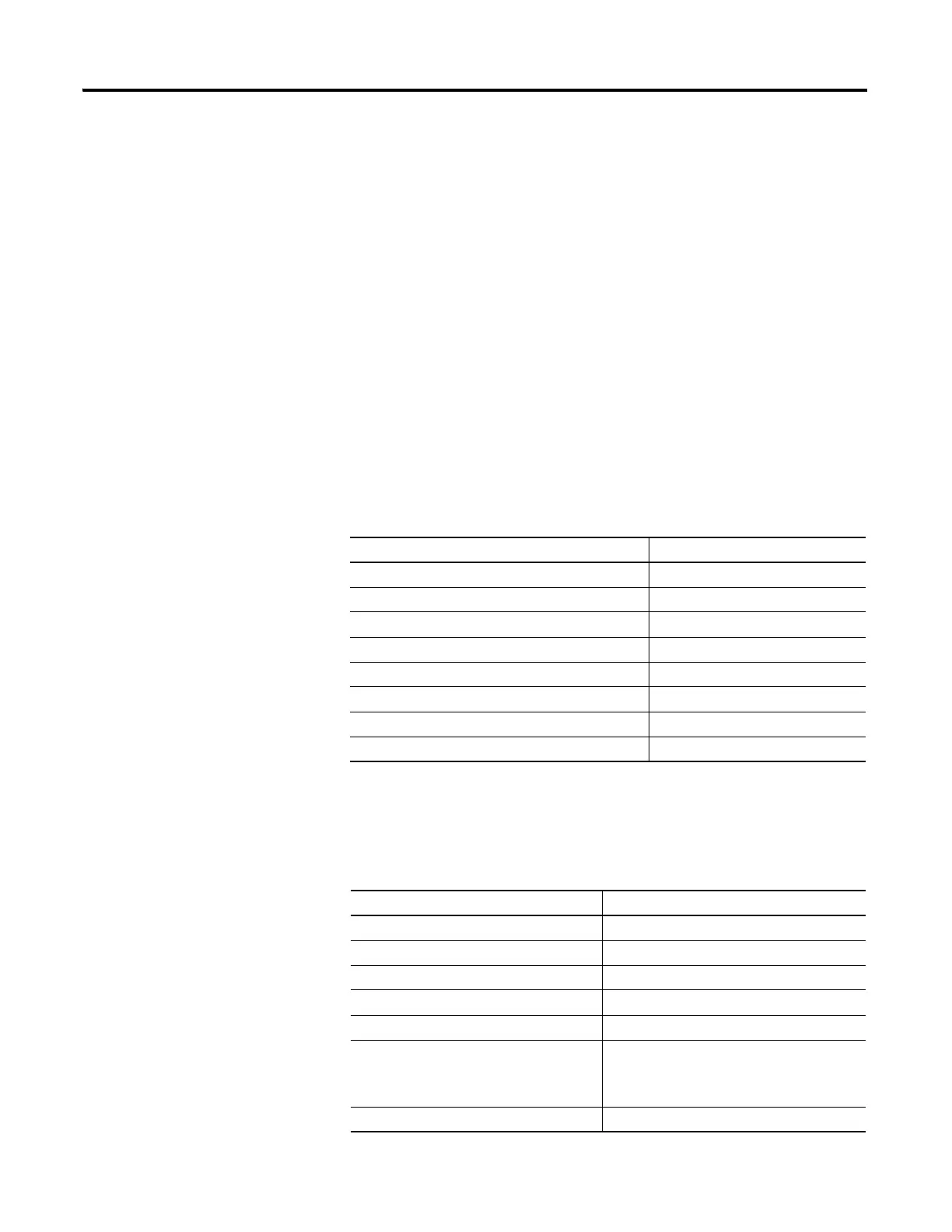
Specialty Modules
For more information about the following 1734 specialty modules, refer to the
installation instructions and user manuals listed in the Related Products and
Documentation section of this manual.
Power Supplies, Wiring
Base Assemblies, and
Miscellaneous Modules
For more information about the following, refer to the installation instructions
and user manuals listed in the Related Products and Documentation section of
this manual.
Module Description Cat. No.
5V Encoder/Counter Module 1734-IJ
24V Encoder/Counter Module 1734-IK
24V Very High-speed Counter Module 1734-VHSC24
5V Very High-speed Counter Module 1734-VHSC5
ASCII RS-232 and RS-485 Module 1734-232ASC, 1734-485ASC
Isolated Thermocouple Input Module 1734-IT2I
RTD Input Module 1734-IR2, 1734-IR2E
Synchronous Serial-interface Encoder Module 1734-SSI
Module Description Cat. No.
Cold-junction Wiring Base Assembly 1734-TBCJC
Field Potential Distributor 1734-FPD
POINT I/O 24V DC Expansion Power Supply 1734-EP24DC
POINT I/O Common Terminal Module 1734-CTM
POINT I/O Voltage Terminal Module 1734-VTM
Wiring Base Assembly 1734-TB, 1734-TBS,
1734-TB3, 1734-TB3S,
1734-TOP, 1734-TOPS,
1734-TOP3, 1734-TOP3S
Address Reserve Module 1734-ARM

 Loading...


