Rockwell Automation Publication 1734-UM001E-EN-P - July 2013
78 Install POINTBlock I/O Modules
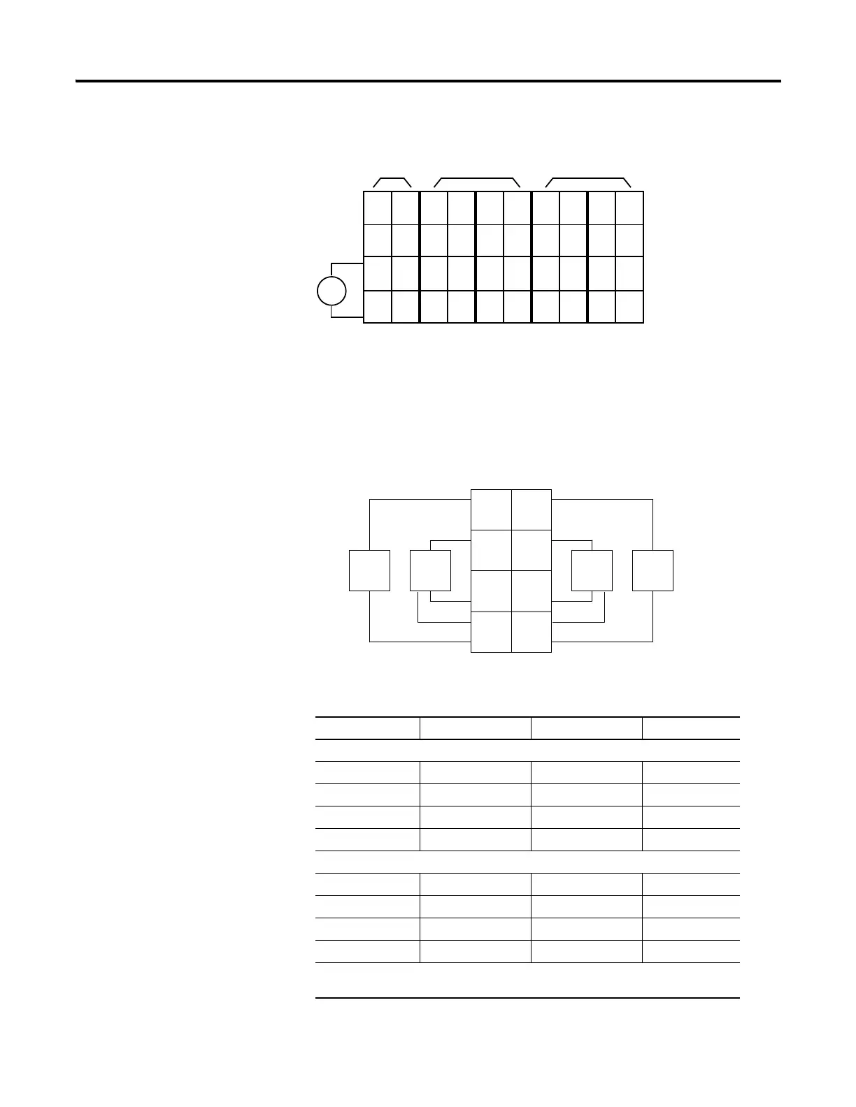
8 Input/8 Output Module Wiring Diagram
Sink Input Wiring
Diagram
Channel Input Terminal Common Voltage
Remote Termination Block 1
00 4 6
11 5 7
22 4 6
33 5 7
Remote Termination Block 2
40 4 6
51 5 7
62 4 6
73 5 7
Connect common on 3-wire proximity switches.
12/24V DC is supplied through the internal power bus.
V dc
NC
NC
Cin
Vin
12/24V dc
Power
NC = No Connection Chas Gnd = Chassis Ground
C = Common V = Supply
NC
NC
Cin
Vin
0
2
C
V
1
3
C
V
4
6
C
V
5
7
C
V
0
2
C
C
1
3
C
C
4
6
C
C
5
7
C
C
Field
Power
Inputs Outputs
This supply will be connected to the internal power bus.
01
23
45
67
01
23
45
67
01
23
45
67
01
23
45
67
01
23
45
67
RTB 0 RTB 1 RTB 2 RTB 3 RTB 4
Prox
In 0 In 1
In 2
C
VV
C
In 3
Prox ProxProx
V = 12/24V dc
C = Common
3
5
7
01
2
4
6
3-wire2-wire

 Loading...


