Home
Allen-Bradley
Controller
22C-D038A103
Allen-Bradley 22C-D038A103 User Manual
5
of 1
of 1 rating
196 pages
Give review
Manual
Specs
To Next Page
To Next Page
To Previous Page
To Previous Page
Loading...
Rockwell Automation P
ublication 22C-UM001
J-EN-E - January 2
017
13
Installation/
Wiring
Chapter 1
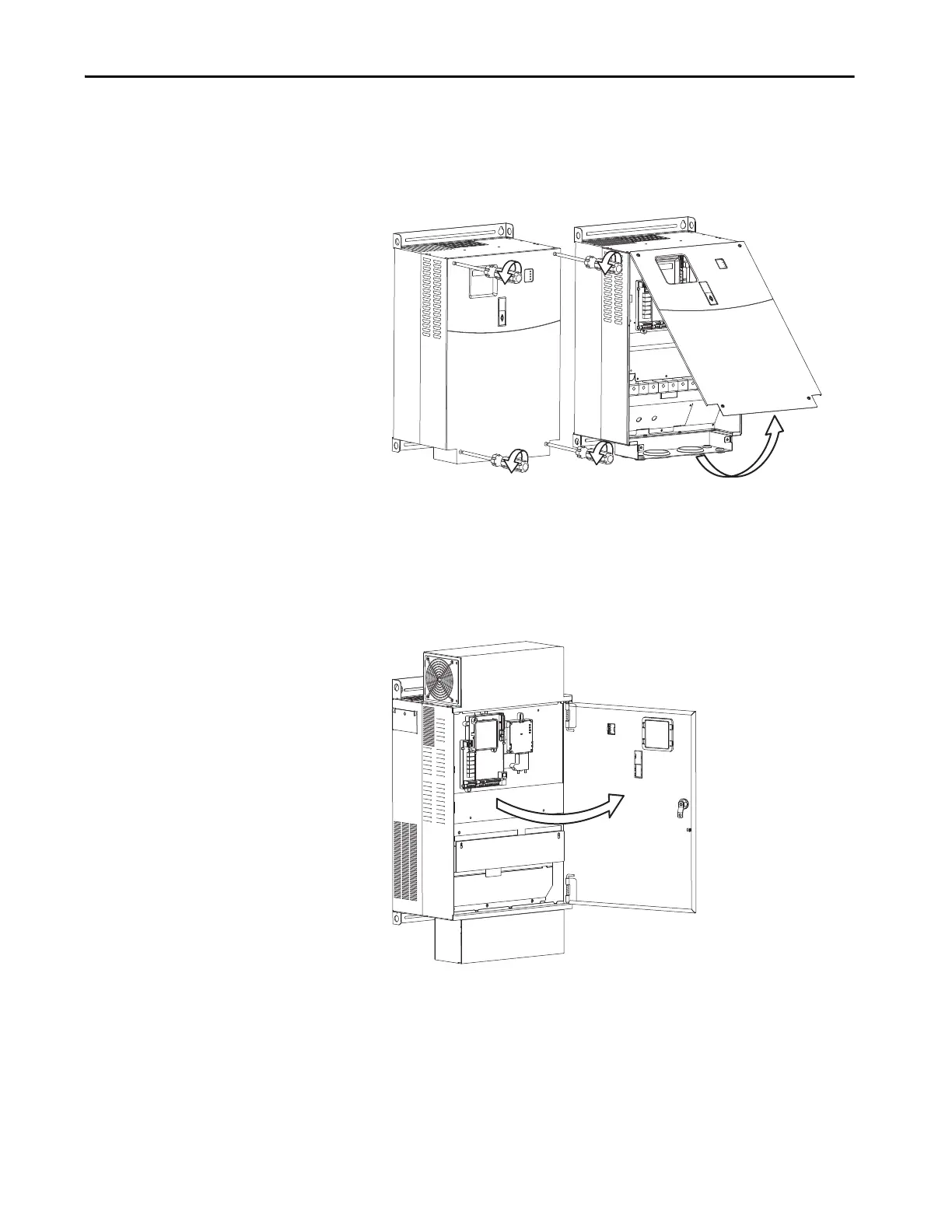
Frame E D
rives
1.
Lo
osen the fou
r capt
ive cover sc
rews.
2.
Pull the bott
om of t
he cover ou
t and u
p to re
lease.
Frame F Driv
es
1.
T
urn the la
tch count
erclock
wise.
2.
Pull on the latch to swin
g the door open.
14
16
Table of Contents
Default Chapter
2
Important User Information
2
Table of Contents
3
Summary of Changes
7
Additional Resources
9
Overview
9
Preface
9
Who Should Use this Manual
9
Drive Frame Sizes
10
Manual Conventions
10
General Precautions
11
Catalog Number Explanation
12
Installation/Wiring
13
Chapter 1 Opening the Cover
14
Frame C Drives
14
Frame D Drives
14
Frame E Drives
15
Frame F Drives
15
Frame G Drives
16
Frame H Drives
16
Mounting Considerations
17
Maximum Surrounding Air Temperature
17
Minimum Mounting Clearances
18
Debris Protection
19
Storage
20
AC Supply Source Considerations
20
Ungrounded Distribution Systems
20
Input Power Conditioning
21
General Grounding Requirements
21
Ground Fault Monitoring
22
Safety Ground - (PE)
22
Motor Ground
22
Shield Termination - SHLD
22
RFI Filter Grounding
22
Fuses and Circuit Breakers
23
Fusing
23
Bulletin 140M (Self-Protected Combination Controller)/Ul489
23
Circuit Breakers
23
Power Wiring
24
Motor Cable Types Acceptable for 200
25
Reflected Wave Protection
26
Output Disconnect
26
Power Terminal Block
27
I/O Wiring Recommendations
30
Motor Start/Stop Precautions
30
Control Wire Types
30
I/O Terminal Block
30
Maximum Control Wire Recommendations
31
I/O Wiring Examples
34
Typical Multiple Drive Connection Examples
38
Start and Speed Reference Control
39
Accel/Decel Selection
40
RS485 Network Wiring
40
On Drive Connections
41
EMC Instructions
41
CE Conformity
41
Low Voltage Directive (2014/35/EU)
41
EMC Directive (2014/30/EU)
41
General Notes
42
Essential Requirements for CE Compliance
42
FCC Instructions
44
FCC Compliance
44
Essential Requirements for FCC Compliance
44
Chapter 2 Prepare for Drive Start-Up
47
Before Applying Power to the Drive
47
Applying Power to the Drive
48
Start, Stop, Direction and Speed Control
48
Integral Keypad
49
Operator Keys
49
LED Status Indicators
50
LCD Display
50
Viewing and Editing Parameters
51
Keypad Hand-Off-Auto Functions
52
Hand-Off-Auto Mode
52
Local/Remote Mode
53
Auto/Manual Mode
54
No Function Mode
55
Start up
47
Chapter 3 About Parameters
57
Parameter Organization
58
Basic Display Group
60
Basic Program Group
63
Terminal Block Group
68
Communications Group
81
Advanced Program Group
85
Aux Relay Card Group
100
Advanced Display Group
104
Parameter Cross Reference by Name
112
Rockwell Automation Publication 22C-UM001J-EN-E - January
113
Programming and Parameters
57
Chapter 4 Drive Status
115
LED Indications
115
Faults
115
Manually Clearing Faults
116
Auto Restart (Reset/Run)
117
Fault Descriptions
117
Common Symptoms and Corrective Actions
119
Motor Does Not Start
119
Terminal Block
120
Drive Does Not Start from Integral Keypad
120
Motor And/Or Drive will Not Accelerate to Commanded Speed
121
Motor Operation Is Unstable
121
Drive will Not Reverse Motor Direction
121
Drive Does Not Power up
122
Drive, Fuse & Circuit Breaker Ratings
123
Appendix A
123
Fusing
123
Circuit Breakers
123
Specifications
124
Powerflex 400 Watts Loss (Rated Load, Speed & PWM)
129
Input Power Connections
130
Product Selection
131
Appendix B Product Dimensions
138
Appendix C
155
DSI Cable Accessories
155
Connectivity Examples
156
Connectivity Guidelines
155
Appendix D Damper Control Setup
159
PID Setup
159
PID Control Loop
159
Exclusive Control
160
Trim Control
161
PID Reference and Feedback
161
Analog PID Reference Signals
163
PID Deadband
164
PID Preload
164
PID Limits
164
PID Gains
164
Guidelines for Adjusting the PID Gains
165
Auxiliary Motor Control Setup
167
Appendix E Network Wiring
171
Parameter Configuration
172
Supported Modbus Function Codes
172
Writing (06) Logic Command Data
172
Writing (06) Reference
173
Reading (03) Logic Status Data
174
Reading (03) Feedback
174
Reading (03) Drive Error Codes
174
Reading (03) and Writing (06) Drive Parameters
175
Additional Information
175
Appendix F Understanding Metasys N2
177
Metasys N2 Virtual Objects
177
Metasys N2 Data Types
178
Network Points
179
Using Percent (%) for the Reference
182
Using Metasys Configurable Objects to Access Parameters
183
Reading Parameter Values
183
Writing Parameter Values
184
Appendix G P1-FLN Points
185
Network Points
186
Using Percent (%) for the Reference
190
Using P1 Configurable Points to Access Parameters
190
Reading Parameter Values
190
Writing Parameter Values
191
Understanding P1-FLN
185
Index
193
Rockwell Automation Publication 22C-UM001J-EN-E - January
194
5
Based on 1 rating
Ask a question
Give review
Questions and Answers:
Need help?
Do you have a question about the Allen-Bradley 22C-D038A103 and is the answer not in the manual?
Ask a question
Allen-Bradley 22C-D038A103 Specifications
General
Brand
Allen-Bradley
Model
22C-D038A103
Category
Controller
Language
English
Related product manuals
Allen-Bradley 22C-D030N103
196 pages
Allen-Bradley 22C-D012N103
196 pages
Allen-Bradley 22C-D017N103
196 pages
Allen-Bradley 22C-D022N103
196 pages
Allen-Bradley 22C-D045A103
196 pages
Allen-Bradley 22C-D060A103
196 pages
Allen-Bradley 22C-D072A103
196 pages
Allen-Bradley 22C-D088A103
196 pages
Allen-Bradley 22C-D6P0N103
196 pages
Allen-Bradley 22C-D208A103
196 pages
Allen-Bradley 22C-B012N103
196 pages
Allen-Bradley 22A-A4P5N104
12 pages
 Loading...