170 Rockwell Automation Publication 22C-UM001J-EN-E - January 2017
Appendix E Modbus RTU Protocol
Standard RS485 wiring practices apply. Termination resistors need to be
applied at each end of the network cable. RS485 repeaters may need to be used
for long cable runs, or if greater than 32 nodes are needed on the network.
Parameter Configuration
The following PowerFlex 400 parameters are used to configure the drive to
operate on a network.
Supported Modbus Function
Codes
The peripheral interface (DSI) used on PowerFlex 400 drives supports some of
the Modbus function codes.
Writing (06) Logic Command
Data
The PowerFlex 400 drive can be controlled via the network by sending
Function Code 06 writes to register address 8192 (Logic Command). P036
[Start Source] must be set to 5 “Comm Port” in order to accept the commands.
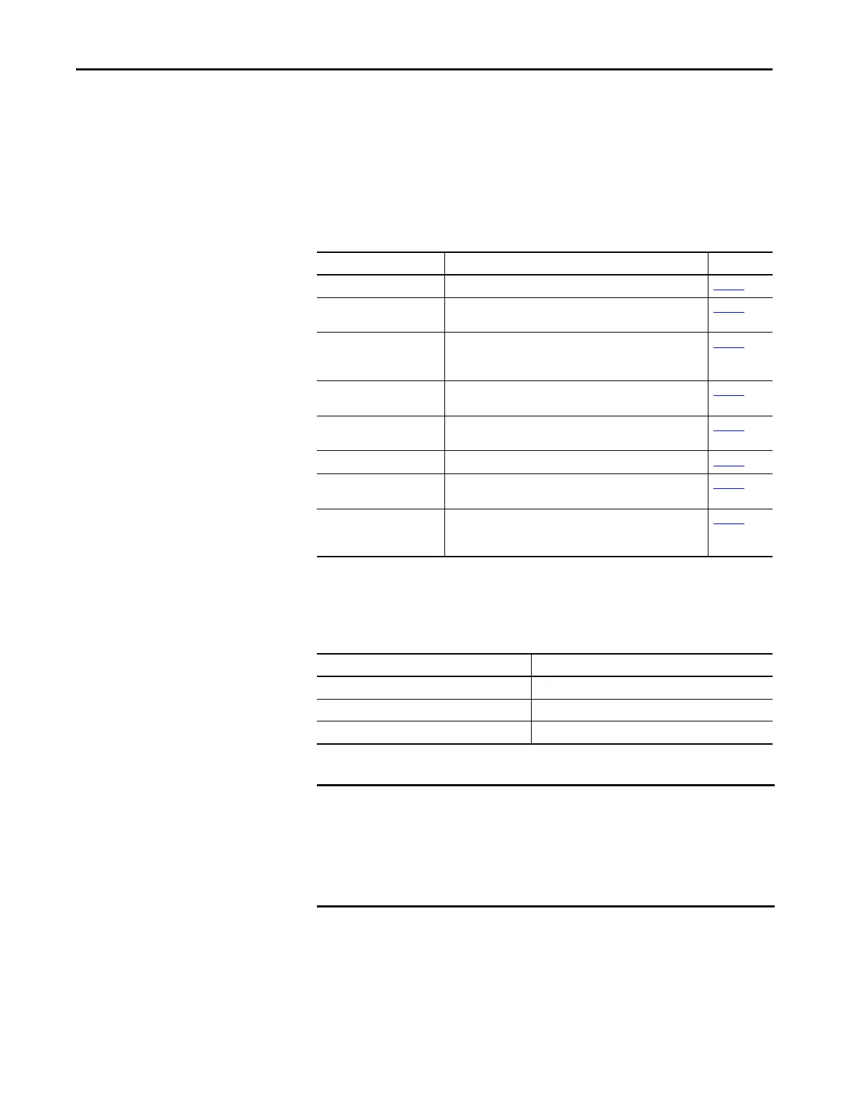
Parameter Details Reference
P036 [Start Source] Set to 5 “RS485 (DSI) Port” if Start is controlled from the network. page 62
P038 [Speed Reference] Set to 5 “RS485 (DSI) Port” if the Speed Reference is controlled
from the network.
page 63
C102 [Comm Format] Sets the transmission mode, data bits, parity and stop bits for the
RS485 (DSI) Port. All nodes on the network must be set to the
same setting.
page 79
C103 [Comm Data Rate] Sets the data rate for the RS485 (DSI) Port. All nodes on the
network must be set to the same data rate.
page 79
C104 [Comm Node Addr] Sets the node address for the drive on the network. Each device
on the network requires a unique node address.
page 80
C105 [Comm Loss Action] Selects the drive’s response to communication problems. page 80
C106 [Comm Loss Time] Sets the time that the drive will remain in communication loss
before the drive implements C105 [Comm Loss Action].
page 80
C107 [Comm Write Mode] Determines whether parameter changes made over
communication port are saved or stored in RAM only. If they are
stored in RAM, the values will be lost at power-down.
page 80
Modbus Function Code Command
03 Read Holding Registers
06 Preset (Write) Single Register
16 (10 Hexadecimal) Preset (Write) Multiple Registers
IMPORTANT Modbus devices can be 0-based (registers are numbered starting at 0) or 1-
based (registers are numbered starting at 1). Depending on the Modbus
Master used, the register addresses listed on the following pages may need
to be offset by +1. For example, Logic Command may be register address
8192 for some master devices (e.g. ProSoft 3150-MCM SLC Modbus scanner)
and 8193 for others (e.g. PanelViews).
 Loading...