EasyManuals Logo
Home>Allen-Bradley>Controller>22C-D038A103

Allen-Bradley 22C-D038A103 User Manual

Allen-Bradley 22C-D038A103
196 pages
To Next Page IconTo Next Page
To Previous Page IconTo Previous Page
Page #18 background imageLoading...
Page #18 background image
16 Rockwell Automation Publication 22C-UM001J-EN-E - January 2017
Chapter 1 Installation/Wiring
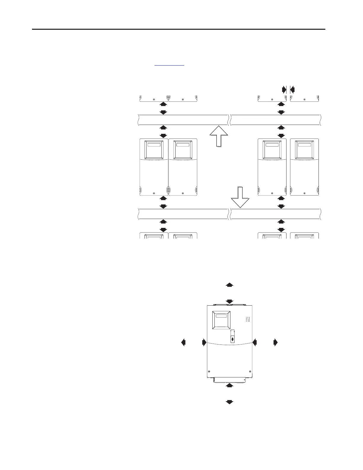
Minimum Mounting Clearances
Refer to Appendix B for mounting dimensions.
Figure 1 - Frame C Mounting Clearances
Figure 2 - Frames D & E Mounting Clearances
120 mm
(4.7 in.)
120 mm
(4.7 in.)
25 mm
(1.0 in.)
120 mm
(4.7 in.)
120 mm
(4.7 in.)
120 mm
(4.7 in.)
120 mm
(4.7 in.)
120 mm
(4.7 in.)
120 mm
(4.7 in.)
Closest object that may
restrict air flow
through the drive heat
sink and chassis.
Mounting Option A
No clearance required
between drives.
Mounting Option B
150 mm
(6.0 in.)
150 mm
(6.0 in.)
50 mm
(2.0 in.)
50 mm
(2.0 in.)

Table of Contents

Questions and Answers:

Question and Answer IconNeed help?

Do you have a question about the Allen-Bradley 22C-D038A103 and is the answer not in the manual?

Allen-Bradley 22C-D038A103 Specifications

General IconGeneral
BrandAllen-Bradley
Model22C-D038A103
CategoryController
LanguageEnglish

Related product manuals