32 Rockwell Automation Publication 22C-UM001J-EN-E - January 2017
Chapter 1 Installation/Wiring
I/O Wiring Examples
IMPORTANT If using auxiliary motor control, ensure that wiring and parameter
configuration are correct before wiring contactor outputs. All relays on the
Auxiliary Relay Card will energize on power-up by default. Failure to verify
proper wiring and parameter configuration can result in improper motor
operation or drive damage. Refer to Appendix D
for more details.
Table 11 - User Installed Relay Board Terminal Designations
No. Signal Default Description Param.
3A #3 Relay N.O. Ready/Fault Normally open contact for Number 3 Output Relay R221
3B #3 Relay Common – Common for Number 3 Output Relay
4A #4 Relay N.O. Ready/Fault Normally open contact for Number 4 Output Relay R224
4B #4 Relay Common – Common for Number 4 Output Relay
5A #5 Relay N.O. Ready/Fault Normally open contact for Number 5 Output Relay R227
5B #5 Relay Common – Common for Number 5 Output Relay
6A #6 Relay N.O. Ready/Fault Normally open contact for Number 6 Output Relay R230
6B #6 Relay Common – Common for Number 6 Output Relay
7A #7 Relay N.O. Ready/Fault Normally open contact for Number 7 Output Relay R233
7B #7 Relay Common – Common for Number 7 Output Relay
8A #8 Relay N.O. Ready/Fault Normally open contact for Number 8 Output Relay R236
8B #8 Relay Common – Common for Number 8 Output Relay
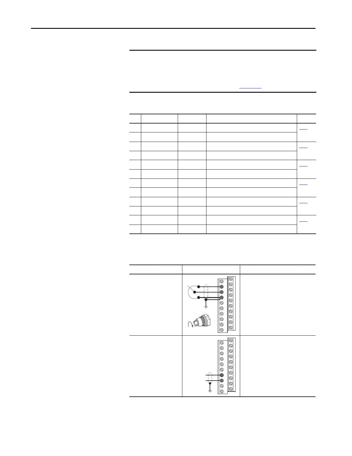
Input/Output Connection Example Required Settings
Potentiometer
1-10k Ohm Potentiometer
Recommended
(2 Watt Minimum)
DIP Switch
AI1 = 10V
Parameters
P038 [Speed Reference] = 2 “Analog In1”
T069 [Analog In 1 Sel] = 2 “0-10V”
Scaling
T070 [Analog In 1 Lo]
T071 [Analog In 1 Hi]
Check Results
d305 [Analog In 1]
Analog Input
Bipolar Speed Reference,
±10V Input
DIP Switch
AI2 = 10V
Parameters
P038 [Speed Reference] = 3 “Analog In2”
T073 [Analog In 2 Sel] = 3 “-10 to +10V”
Scaling
T074 [Analog In 2 Lo]
T075 [Analog In 2 Hi]
Check Results
d306 [Analog In 2]
 Loading...