116 Rockwell Automation Publication 6000-UM002E-EN-P - April 2018
Chapter 5 Preventative Maintenance and Component Replacement
3. Disconnect the fiber optic wires from A/B/C Phase board.
4. Disconnect the PLC communication cable from the CPU board.
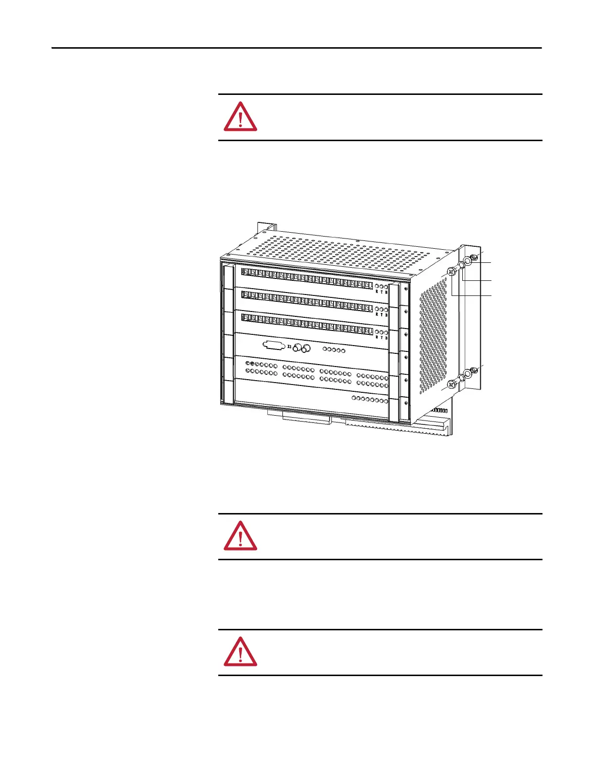
5. Remove four M6 x 12 bolts, and remove the Control Unit.
Figure 49 - Remove Retaining Screws of Control Unit
6. Install the new Control Unit in reverse order of removal. Refer to
Electrical Drawings for exact placement of all wires and connections.
Replace a Control Board
1. Turn off all the control power, turn off the UPS, and confirm the LV
Control cabinet is unenergized before operation.
If applicable, remove the fiber optic wires.
ATTENTION: When removing the fiber optic cables, be careful to prevent the
cables from straining or crimping as a resulting loss in light transmission will
impact performance.
Washer
Lock washer
M6 x 12 bolt
ATTENTION: Some circuit boards can be destroyed by static charges. Use of
damaged circuit boards may also damage related components. Use a grounding
wrist strap when handling sensitive circuit boards.
ATTENTION: When removing the fiber optic cables, be careful to prevent the
cables from straining or crimping as a resulting loss in light transmission will
impact performance.

 Loading...


