120 Rockwell Automation Publication 6000-UM002E-EN-P - April 2018
Chapter 5 Preventative Maintenance and Component Replacement
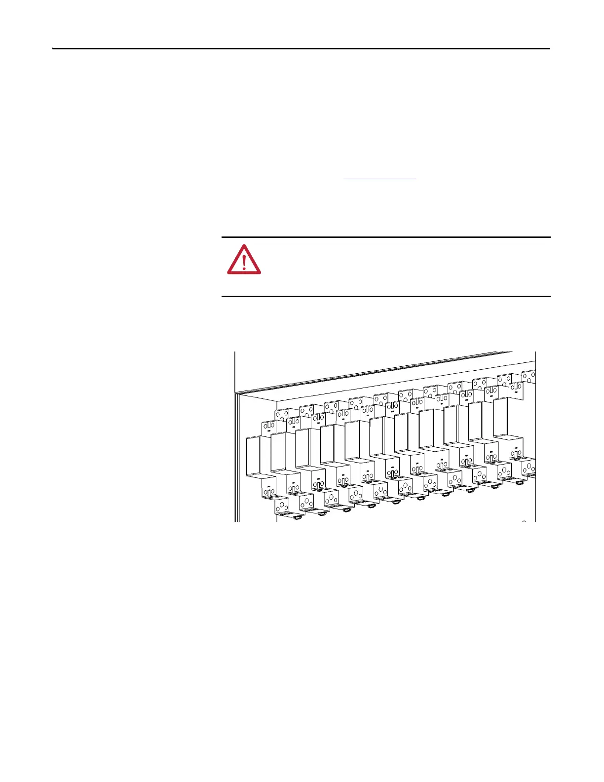
Replace LV Control Relays
1. Open the LV Control cabinet door.
Figure 50 - LV Control Relay Location
2. Loosen the top and bottom screws and remove the wires on the control
relay.
The following HMI components can be replaced:
• Logic Module
• Display Module
• Bezel
• Backlight
• Battery
See publication 2711P-UM006_-EN-P
for further information.
ATTENTION: Always perform Power Lockout procedure before servicing
equipment. Verify with a hot stick or appropriate voltage measuring device that
all circuits are voltage free. Failure to do so may result in severe burns, injury, or
death.

 Loading...


