Rockwell Automation Publication 6000-UM002E-EN-P - April 2018 95
Preventative Maintenance and Component Replacement Chapter 5
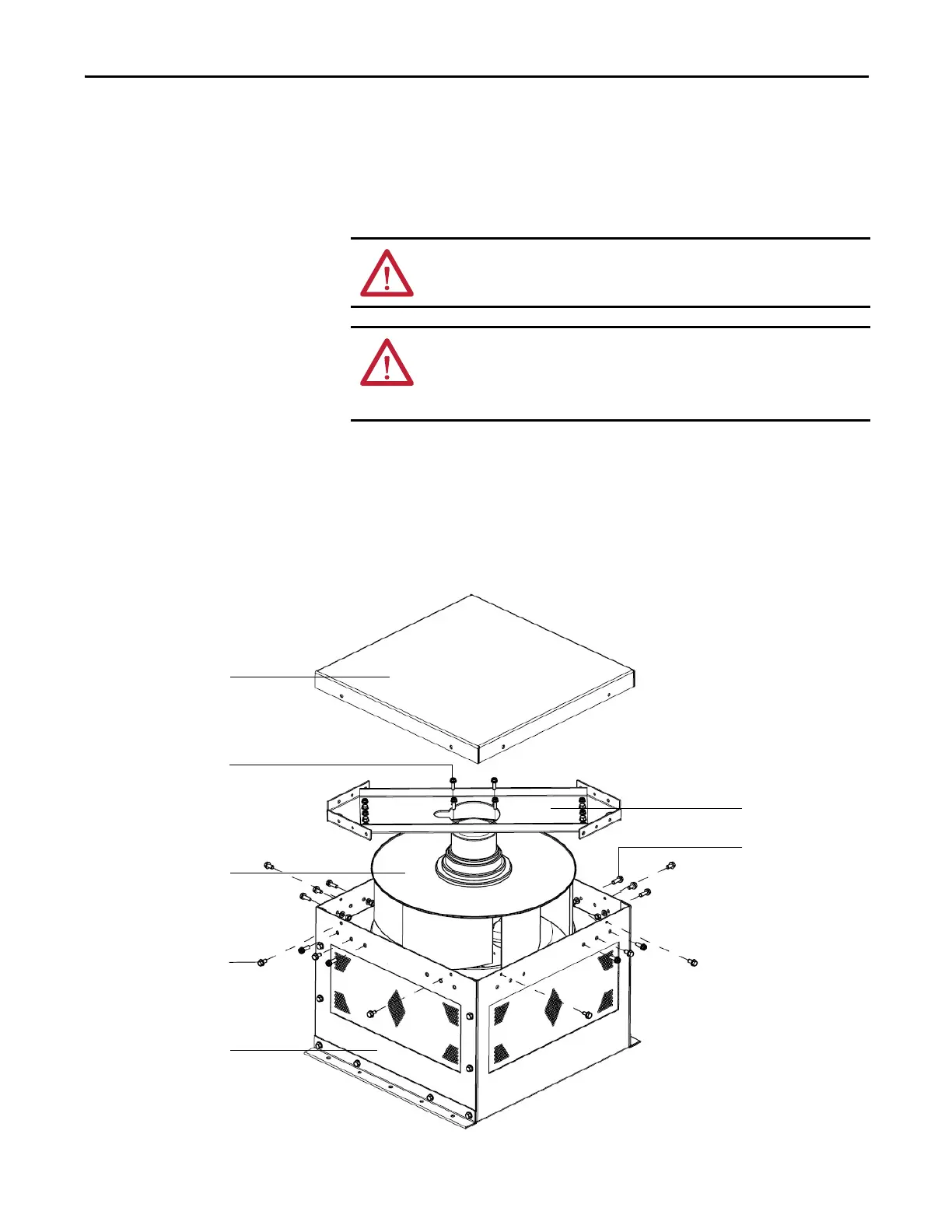
Replace Top Mounted Cooling Fans
There are two types of top fan housings. The top fan housing consists of a motor
and impeller assembly. To replace the fan, it is necessary to remove the fan
housing lid.
Replace Fan for Type A Fan Housing
1. Remove and retain four tapping screws around the fan housing lid, and
remove the lid.
2. Remove and retain eight M6 x 12 hexagon screws from the fan housing
assembly which connect to the fan support bracket.
ATTENTION: Fan replacement requires working at a significant height from the
floor. Complete this procedure on a safe, stable platform.
ATTENTION: Always perform Power Lockout procedure before servicing
equipment. Verify with a hot stick or appropriate voltage measuring device that
all circuits are voltage free. Failure to do so may result in severe burns, injury, or
death.
M6 x 20 integration
hexagon bolt (4)
M6 x 12 hexagon screw (8)
Fan housing lid
Fan support bracket
Fan assembly
Fan housing assembly
M6 x 12 hexagon screw (12)

 Loading...


