118 Rockwell Automation Publication 6000-UM002E-EN-P - April 2018
Chapter 5 Preventative Maintenance and Component Replacement
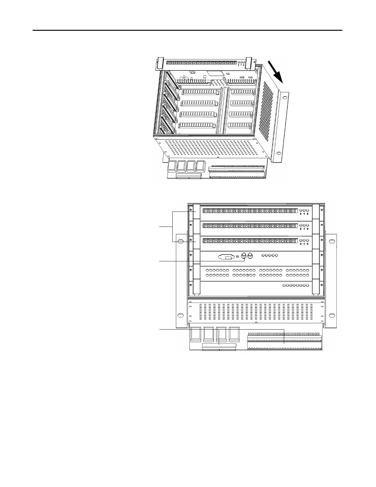
4. Install the new boards in the reverse order of removal.
5. Refer to the Electrical Drawings for reconnecting the fiber optic wires.
Inspect the HMI
1. Verify the input and output cables and communication cables are hand-
tight.
2. Power up the HMI.
3. Verify the HMI display is operating normally.
Connect fiber optic wires here
(Refer to electrical drawings)
Reconnect the PLC cable
Reconnect the bottom terminal

 Loading...


