Rockwell Automation Publication 6000-UM002E-EN-P - April 2018 99
Preventative Maintenance and Component Replacement Chapter 5
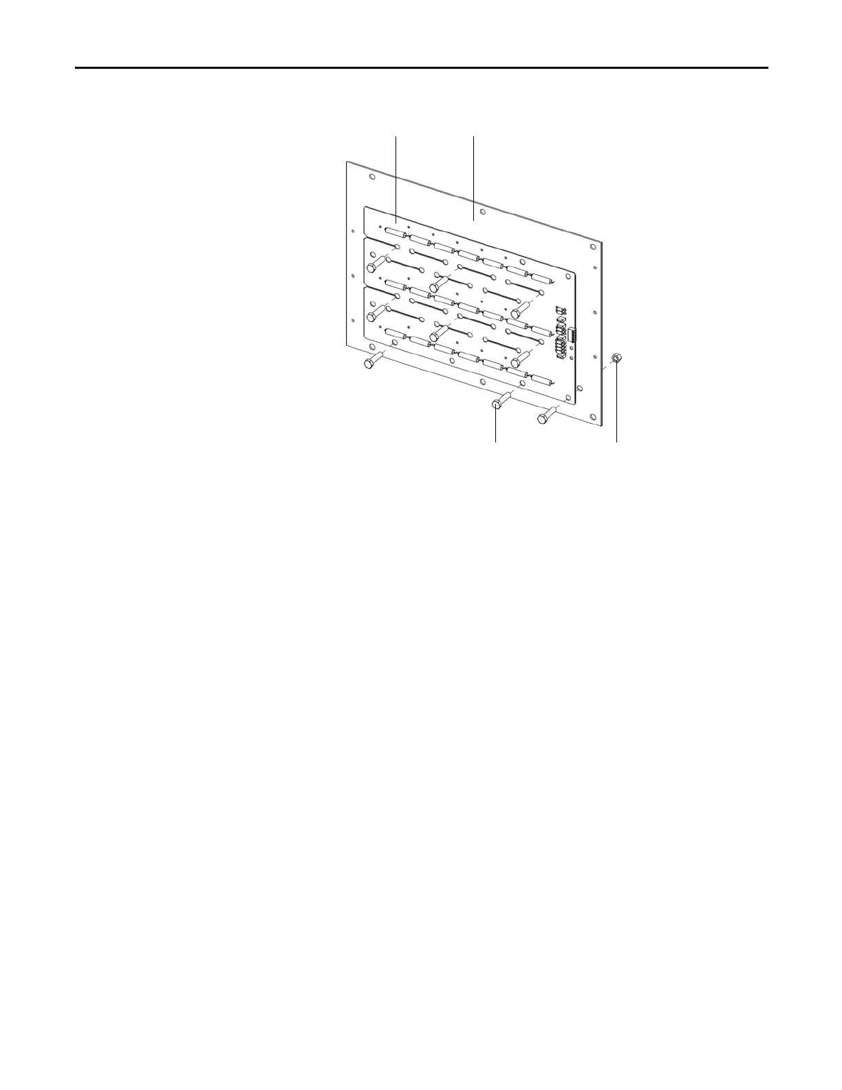
Figure 32 - Remove the Voltage Sensing Board from the Insulation Board
4. Install the new Voltage Sensing Board to the Insulation Board in reverse
order of removal.
5. Reinstall the Insulation Board to the cabinet side sheet in reverse order of
removal.
6. Reconnect the input and output cables according to the Electrical
Drawings.
Inspect Door Position Limit Switch
Check for obvious signs of damage, dust, or foreign material. Remove any dirt or
foreign material. Wipe components with an anti-static cloth, where applicable.
Check the aviation plug has a hand-tight connection.
Nylon M10 nut (6)Nylon M10 x 40 bolt (6)
Insulation BoardVoltage Sensing Board

 Loading...


